


Making the Physical Connections 3-15
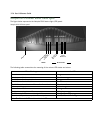
2. Connect one end of one of the RJ-45 cables to the Line 1 port and the other end to your Internet modem’s
Ethernet port. DO NOT CONNECT IT DIRECTLY TO A TELCO LINE OUTLET.
3. Connect one end of one of the RJ-45 cables to any of the Ethernet hub ports on the router, and the other
end to the Ethernet port of your PC.
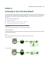
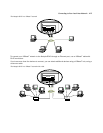
If you are connecting the router to an existing Ethernet hub, use a cross-over cable.
You should now have: the power adapter plugged in; the Ethernet cable connected between the router and
your computer; and the Line cable connected between the router and your Internet modem.
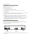
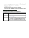
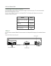
Netopia R910 Ethernet Router back panel ports
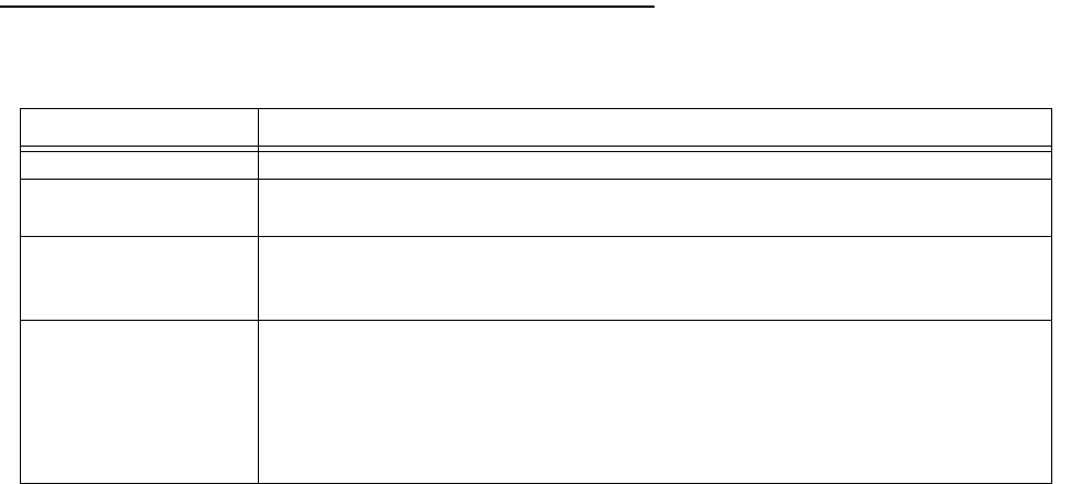
The following table describes all the Netopia R910 Ethernet Router back panel ports.
Port Description
Power port A mini-DIN8 power adapter cable connection.
Line port The dedicated Ethernet port for your connection to your Internet connection
device’s Ethernet port.
Console port A DB-9 console port for a direct serial connection to the console screens. You
can use this if you are an experienced user. See “Connecting a console cable to
your router” on page 6-33.
4-port Ethernet hub Four Ethernet jacks. You will use one of these to configure the Netopia R910.
For a new installation, use the Ethernet connection. Alternatively, you can use
the console connection to run console-based management using a direct serial
connection. You can either connect your computer directly to any of the Ethernet
ports on the router, or connect both your computer and the router to an existing
Ethernet hub on your LAN.