


3-16 User’s Reference Guide
Netopia R910 Ethernet Router status lights
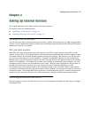
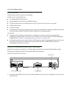
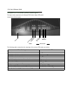
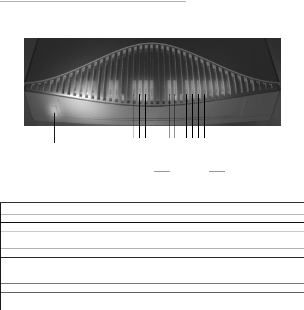
The figure below represents the Netopia R910 status light (LED) panel.
Netopia R910 LED front panel
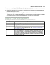
The following table summarizes the meaning of the various LED states and colors:
When this happens... the LEDs...
Power is on 1 is green.
Data is transmitted or received 8 flashes orange.
The WAN interface is operational 9 is green.
The WAN interface is inactive 9 is off.
The WAN interface detects a failure after line activation 9 flashes red.
Calls are setting up 10 flashes green.
Data calls connect 10 is green.
The line is carrying data traffic 10 flashes orange.
The Ethernet port is connected to the LAN 14, 15, 16, and 17 are green.
There is activity on the respective Ethernet ports 14, 15, 16, and 17 flash green.
Note: The Channel 2 LED and the unlabeled LEDs are not used.
8 9 10 12 13 1415 1617
Management
Ready
Channel 1
Link/
Receive
Collision
Traffic
WAN Ethernet
Power
1