


Getting Started • 35
3.4.2 Removing HDD/FFD from cPCI-6760DK/P5
• Remove the four screws from the bottom side that mounts on the copper
stand-offs.
• Remove the 44-pin ribbon cable from CN2 of the cPCI-6760DK/P5 and
remove the cable from the HDD.
• Remove the copper stand-offs from the HDD.
3.5 Device Connection for OS Installation
This section describes how to get started with installation of an OS on to the
cPCI-6760DK/P5 CPU module. The easiest way to install an OS is by
connecting an ATAPI CD-ROM.
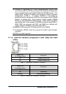
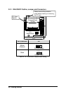
3.5.1 Using the cPCI-6760DK/P5 with ADLINK’s cBP-6108 and
6515 series backplane
Since the cBP-6108 and 6515 series backplane have direct IDE connection
from J3/P3 and J5/P5 on the rear I/O interface, and the pin assignments are
compatible with that of the cPCI-6760DK/P5 series product. Users can
easily connect a 40-pin ribbon cable into the IDE interface on the rear side of
backplane. Then connect the other end of the cable into an ATAPI CD-ROM.
Because the primary IDE interface is wired to J3 and then goes to be used by
the DB-6760J3 daughter board, users can only connect an
IDE cable on the
secondary IDE interface on the backplane. If users have installed a 2.5” ATA
HDD or CF card on the front board, it is recommend that the master/slave
setting on CD-ROM be adjusted to prevent any conflicts.
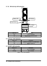
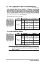
3.5.2 Using the cPCI-6760DK/P5 on other backplanes
For backplanes, which are not compatible with the pin assignments of J5/P5
IDE interface of the cPCI-6760DK/P5, users can connect a 40-pin ribbon
cable onto the
Secondary IDE interface
on the cPCI-R6760D or
cPCI-R6760S rear board and then connect the other end of the ribbon cable
onto the ATAPI CD-ROM. If users have installed a 2.5” ATA HDD or a CF
card on the front board, it is recommended that the master/slave setting on
the CD-ROM be adjusted to prevent any conflicts.