


Getting Started • 37
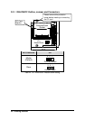
3.6.3 LAN1, LAN2 Front and Rear I/O Connecting Selection
There are two DIPswitches on the solder side of the cPCI-6760DK/P5.
Those switches were originally designed to supports dual Ethernet
connection both on the front and rear I/O’s on the cPCI-6760D, however; with
the cPCI-6760DK/P5, it uses the DB-6760J3 to re-direct the rear I/O signals
on J3 to the front, therefore there is no LAN1 or LAN2 Ethernet available on
rear I/O. Please keep these switches set as factory default to enable
Ethernet functionalities on the cPCI-6760DK/P5.
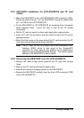
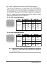
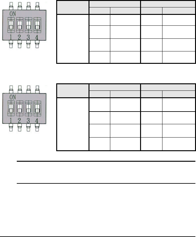
S1, S2: LAN1 Connecting Selection
Switch S1 Switch S2 LAN 1
Connecting
Pin# State Pin# State
S1-1 ON S2-1 OFF
S1-2 ON S2-2 OFF
S1-3 ON S2-3 OFF
Front I/O
Enable
S1-4 ON S2-4 OFF
Table 23: LAN1 Connecting Selection
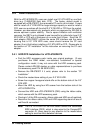
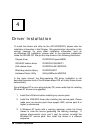
S3, S4: LAN2 Connecting Selection
Switch S3 Switch S4 LAN 2
Connecting
Pin# State Pin# State
S3-1 ON S4-1 OFF
S3-2 ON S4-2 OFF
S3-3 ON S4-3 OFF
Front I/O
Enable
S3-4 ON S4-4 OFF
Table 24: LAN2 Connecting Selection
M DO NOT set S1 and S2 to “ON” or S3 and S4 to “ON” at the
same time. It may cause Ethernet malfunction or damage the
board or devices.