


4-42 Service Manual
24xx
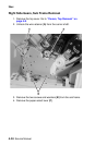
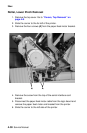
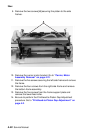
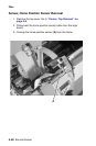
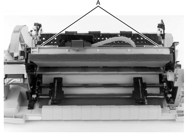
9. Remove the two screws [A] securing the platen to the side
frames.
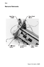
10. Remove the carrier motor bracket. Go to “Carrier, Motor
Assembly Removal” on page 4-21.
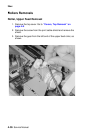
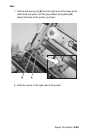
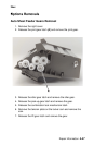
11. Remove the five screws securing the left side frame and remove
the frame.
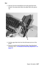
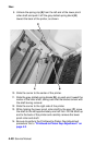
12. Remove the four screws from the right side frame and remove
the bottom frame assembly.
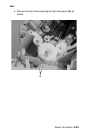
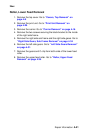
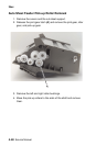
13. Remove the five screws from the frame support plate and
remove the lower feed roller.
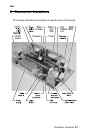
14. Be sure to perform the Printhead-to-Platen Gap Adjustment
procedure. Go to “Printhead-to-Platen Gap Adjustment” on
page 4-2.