


4-14 Service Manual
24xx
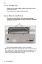
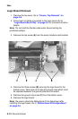
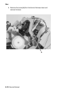
Logic Board Removal
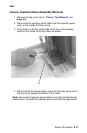
1. Remove the top cover. Go to “Covers, Top Removal” on
page 4-8.
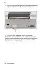
2. Disconnect all cables connected to the logic board. Go to
“Logic Board (9w & 24w)” on page 5-3, for connector location
details.
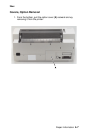
Note: Do not twist the flexible cable when disconnecting the
printhead cable(s).
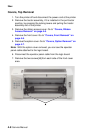
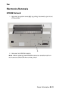
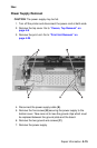
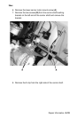
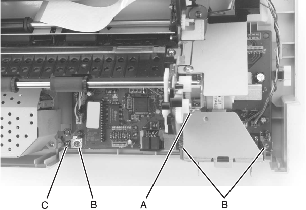
3. Remove the top screw [A] from the serial interface card bracket.
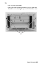
4. Remove the three screws [B] securing the logic board to the
bottom cover. Take care not to lose the ground clips which must
be replaced between the ground plate and the board.
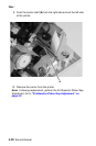
5. Remove the ground clip screw [C] from the bottom cover.
6. Remove the logic board.
Note: Be sure to check the Bidirectional Print Adjustment after
installing the logic board. Go to “Bidirectional Print Adjustment”
on page 4-4.