


10
OKIPOS 425S
|
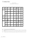
1.4.2 Setting the Interface Board Assembly
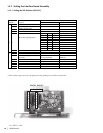
1.4.2.1 Setting the DIP Switches (RS-232C)
A25001.doc
Switch Setting
DIP SW Function
ON OFF
1 Selects the data bit length 7 bits 8 bits
2 Selects between the presence and
absence of parity bits.
Present Absent
3 Selects the parity Even Parity Odd parity
4 Selects the protocol XON / XOFF Ready / Busy
5 6 7 Signaling Speed (BPS)
OFF OFF OFF 1200
OFF OFF ON 2400
OFF ON OFF 4800
OFF ON ON 9600
ON OFF OFF 19200
ON OFF ON Reserved
ON ON OFF Reserved
5 –
7
Selects the signaling speed
ON ON ON Reserved
D
I
P
S
W
1
8 Selects the customer display Connect Disconnect
1 Selects the #6 pin reset signal Enable Disable
2 Selects the #25 pin reset signal Enable Disable
3 Selects the display of received
data errors
Ignore (error conversion
is not performed)
Convert to receive error
characters
4 Selects the mode of circuit test Select Deselect
5 Selects the hard reset signal Enable Disable
6 Selects the software reset signal Enable Disable
7N/A - -
D
I
P
S
W
2
8N/A - -
* There are three types of errors: the parity error, the framing error, and the overrun error.
o425_83.jpg
10 = OFF; 11 = ON
1
2
3
4
5
6
7
8
1
2
3
4
5
6
7
8
DIPSW1 DIPSW2
10 11 10 11