


|
User’s Guide: English 61
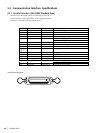
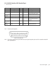
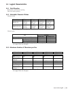
5.3.2 RS-232C Interface (OKI Standard Type)
1 Interface signals
A25013.doc
Pin No. Signal Code Signal Function
1 Protective ground PG - Frame ground
2 Transmitted Data TD From printer Data from printer
3 Received Data RD To printer Data to printer
4 Request to Send RTS From printer Indicates printer cannot receive
data in printer and Customer
Display Busy/Ready protocol
6
(Note 2)
Data Set Ready DSR To printer Indicates that data can be sent
7 Signal Ground SG - Signal ground
20 Data Terminal Ready DTR From Printer Indicates printer cannot receive
data in printer Busy/Ready
protocol
5,8 to 10,11,
12 to 19, 21
to 24
- - - Unused
25
(Note 2)
Initial INIT To Printer Requests printer reset
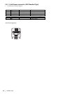
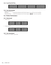
Note 1 Connector pin arrangement
OP425_06.eps
13
25
1
(View from the cable side)
14
Note 2 The enabled or disabled state of the initial state request signals assigned to pins 6 and 25 is selectable with the DIP
SW1-1 and DIP SW1-2.