


94
C200HX/HG/HE Controller Link Units Section 4-3
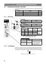
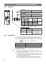
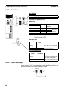
4-3-1 Overview
Node Address
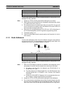
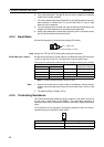
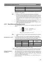
Baud Rate and Operating Level
•Baud Rate
Note Factory default setting is in bold.
Always leave pin 3 OFF.
•Operating Level
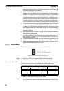
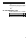
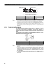
Terminating Resistance
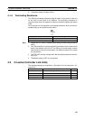
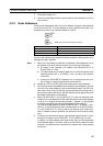
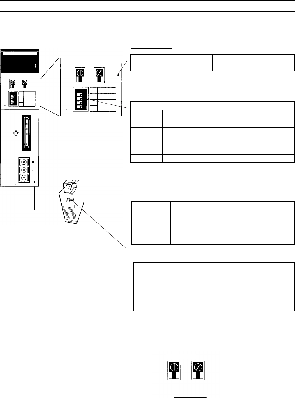
4-3-2 Node Addresses
Set the node addresses of each Unit on the Network using the rotary switches
on the front of the Unit. The node address is used to identify each node in the
Network can be set to any number between 01 and 32.
1
CLK21
X10
1
X10
0
SW1
ON
BD H
BD L
SHLD
RUN
ERC
INS
SD
TER
ERH
M/A
LNK
RD
TER
SW
#0, #1
1
2
3
4
RSV
BAUD
RATE
01
234
1
X10
1
X10
0
SW1
ON
#0, #1
1
2
3
4
RSV
BAUD
RATE
01
234
NODE NO.
Setting range Nodes
01 to 32 (default is 01) All nodes in the Network
Pins Baud rate Maximum
transmis-
sion dis-
tance
Nodes
Pin 1 Pin 2
OFF OFF 2 Mbps 500 m Set same
rate for all
nodes in the
Network.
ON OFF 1 Mbps 800 m
OFF ON 500 Kbps 1 km
ON ON Cannot be set.
Pin 4 Operating
level
Nodes
OFF
(factory
default)
Level 1 All nodes in the Network
Set so that only one Communi-
cations Unit is set to the same
level in the same PLC.
ON Level 0
Bottom
switch
Terminating
resistance
Nodes
OFF
(factory
default)
Not connected All nodes in the Network
Turn ON the terminating resis-
tance at the nodes at both
ends of the Network and turn it
OFF at all other nodes.
ON Connected
1's digit
10's digit
NODE NO.
X10
1
X10
0
01