


103
Repeater Units Section 4-6
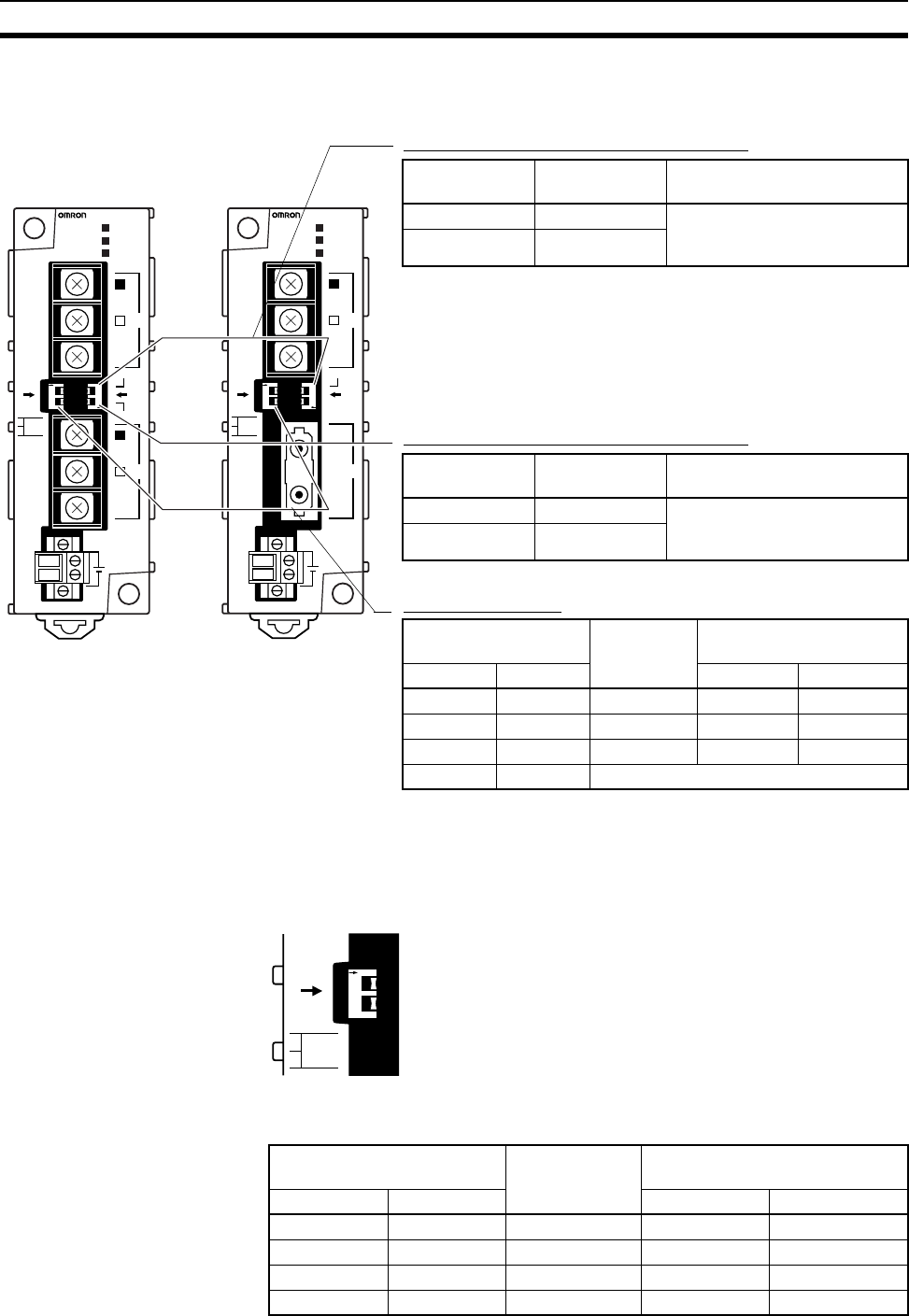
4-6-1 Wire-to-Wire Repeater Unit
Terminating Resistance Switch for SL1
Note The factory default setting is in bold.
Terminating Resistance Switch for SL2
Note The factory default setting is in bold.
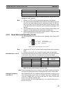
Baud Rate Switch
Note The factory default setting is in bold.
4-6-2 Baud Rates
Set the same baud rates for all nodes on the network using pins 1 and 2 of
DIP switch 1 on the front of the Unit.
The baud rate is set as shown below. The maximum transmission distance
will change according to the baud rate setting.
O
N
1
2
O
N
1
2
DC24V
INPUT
SL1
SL2
T/R2
T/R1
PWR
CS1W-RPT01
BD L
SHLD
BD H
BD L
SHLD
BD H
TER SW
ON
ON
SW1
BAUD
RATE
1
2
TER SW
+
−
O
N
1
2
O
N
1
2
DC24V
INPUT
SL1
SL2
T/R2
T/R1
PWR
CS1W-RPT02
BD L
SHLD
BD H
TER SW
ON
ON
SW1
BAUD
RATE
1
2
+
−
Wire-to-Wire
Repeater Unit
Wire-to-Optical
Repeater Unit
Switch Terminating
resistance
Applicable unit
OFF Not connected Turn ON when the Repeater
Unit is connected to the end of
the Network or a segment.
ON Connected
Switch Terminating
resistance
Applicable unit
OFF Not connected Turn ON when the Repeater
Unit is connected to the end of
the Network or a segment.
ON Connected
Switch Baud rate Maximum transmission
distance
Pin 1 Pin 2 1 segment Network
OFF OFF 2 Mbps 500 m 1.5 km
ON OFF 1 Mbps 800 m 2.4 km
OFF ON 500 Kbps 1 km 3.0 km
ON ON Do not set.
Switch Baud rate Maximum transmission dis-
tance
Pin 1 Pin 2 1 segment Network
OFF OFF 2 Mbps 500 m 1.5 km
ON OFF 1 Mbps 800 m 2.4 km
OFF ON 500 Kbps 1 km 3.0 km
ON ON Do not set. --- ---
O
N
1
2
ON
SW1
BAUD
RATE
1
2