


270
Message Delay Times Section 8-4
8-4-2 C200HX/HG/HE and CQM1H-series PLCs
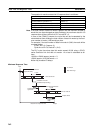
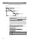
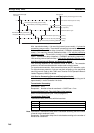
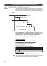
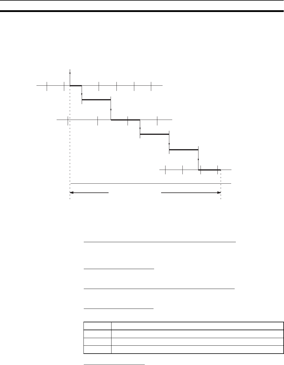
SEND(90) The following diagram indicates the data flow which will yield the maximum
delay time from the time SEND(90) is executed by the user program to the
time the Controller Link Unit stores the data in the destination Unit’s memory.
Max. transmission delay = Link Unit servicing interval (source node) + Trans-
mission processing + Communications cycle time + Transmission delay +
Reception processing + Link Unit servicing interval (destination node).
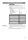
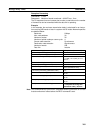
Link Servicing Interval (Source and Destination Nodes)
Link service processing is the same as the PLC’s peripheral servicing and is
approximately 1 ms for Controller Link Units.
Transmission Processing
Responses: Number of words transferred × 0.00125 ms + 3 ms
Communications Cycle Time (with Data Links Inactive)
See 8-2 Communications Cycle Time (on page 251).
Transmission Delay Time
Transmission delay time varies with the baud rate.
Reception Processing
Responses: Number of words transferred × 0.00125 ms + 2.3 ms
Note The I/O response time can increase due to noise or restrictions on the number
of frames that can be transmitted while the data link is operating.
SEND(90)
executed
Link Unit servicing
(source node)
Transmission processing
Communications cycle
Data stored
Link Unit servicing (destination
node)
Transmission delay
Max. transmission delay
Reception processing
Baud rate Transmission delay time
2 Mbps Number of words transferred × 0.08 + 0.112 ms
1 Mbps Number of words transferred × 0.016 + 0.224 ms
500 Kbps Number of words transferred × 0.032 + 0.448 ms