


212
Commands and Responses for C200HX/HG/HE and CQM1H-series PLCs Section 6-6
6-6 Commands and Responses for C200HX/HG/HE and
CQM1H-series PLCs
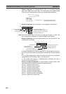
6-6-1 Command Codes
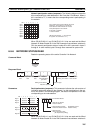
6-6-2 Memory Area Designations
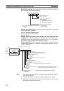
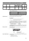
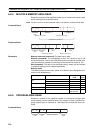
The following table gives the addresses to use when reading or writing PLC
data. The Data area address column gives the normal addresses used in the
PLC program. The Address used in communications column are the
addresses used in CV-mode commands and responses. These addresses
are combined with the memory area codes to specify PLC memory locations.
These addresses are not the same as the actual memory addresses of the
data.
The No. of bytes column specifies the number of bytes to read or write data for
that area. The number of bytes varies for the same area depending on the
memory area code. Actual data area sizes vary with the PLC being used.
Refer to your PLC’s operation manual for specific limits.
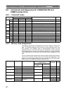
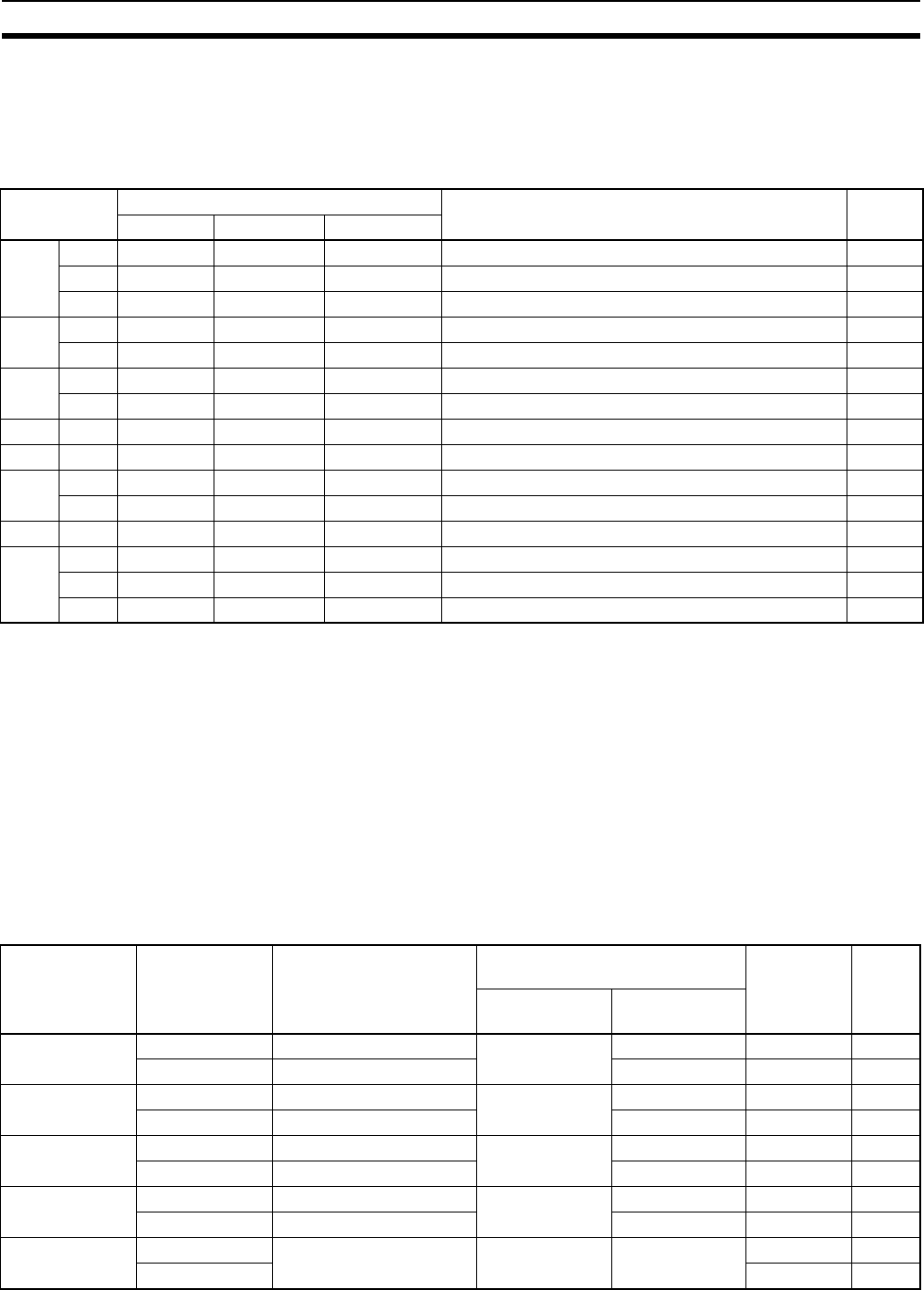
Command
code
PLC mode Name Page
RUN MONITOR PROGRAM
01 01 Valid Valid Valid MEMORY AREA READ 214
02 Valid Valid Valid MEMORY AREA WRITE 215
04 Valid Valid Valid MULTIPLE MEMORY AREA READ 216
03 06 Valid Valid Valid PROGRAM AREA READ 216
07 Not valid Not valid Valid PROGRAM AREA WRITE 217
04 01 Valid Valid Valid RUN 218
02 Valid Valid Valid STOP 218
05 01 Valid Valid Valid CONTROLLER DATA READ 219
06 01 Valid Valid Valid CONTROLLER STATUS READ 220
07 01 Valid Valid Valid CLOCK READ 221
02 Not valid Valid Valid CLOCK WRITE 221
21 01 Valid Valid Valid ERROR CLEAR 222
23 01 Not valid Valid Valid FORCED SET/RESET 222
02 Not valid Valid Valid FORCED SET/RESET CANCEL 223
0A Valid Valid Valid MULTIPLE FORCED STATUS READ 224
Memory area Data Data area address Address used in
communications
Memory
area code
No. of
bytes
1st and 2nd
bytes
3rd byte
IR Area 1, 2
SR Area 1, 2
Bit status 00000 to 51115 0000 to 01FF 00 to 0F 00 1
Word contents 000 to 511 00 to 00 80 2
LR Area Bit status LR 0000 to LR 6315 03E8 to 0427 00 to 0F 00 1
Word contents LR 00 to LR 63 00 to 00 80 2
HR Area Bit status HR 0000 to HR 9915 0428 to 048B 00 to 0F 00 1
Word contents HR 00 to HR 99 00 to 00 80 2
AR Area Bit status AR 0000 to AR 2715 048C to 04A7 00 to 0F 00 1
Word contents AR 000 to AR 27 00 to 00 80 2
Timer/
Counter Area
Status T/C 000
to T/C 511
0000 to 01FF 00 to 00 01 1
PV 81 2