


35
Data Links Procedures Section 2-1
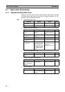
2. Prepare for communications.
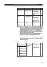
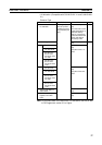
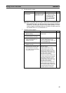
3. Turn ON the power to the PLC.
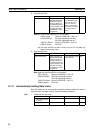
4. Connect the Programming Device.
5. Create I/O tables.
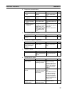
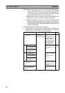
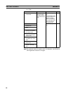
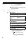
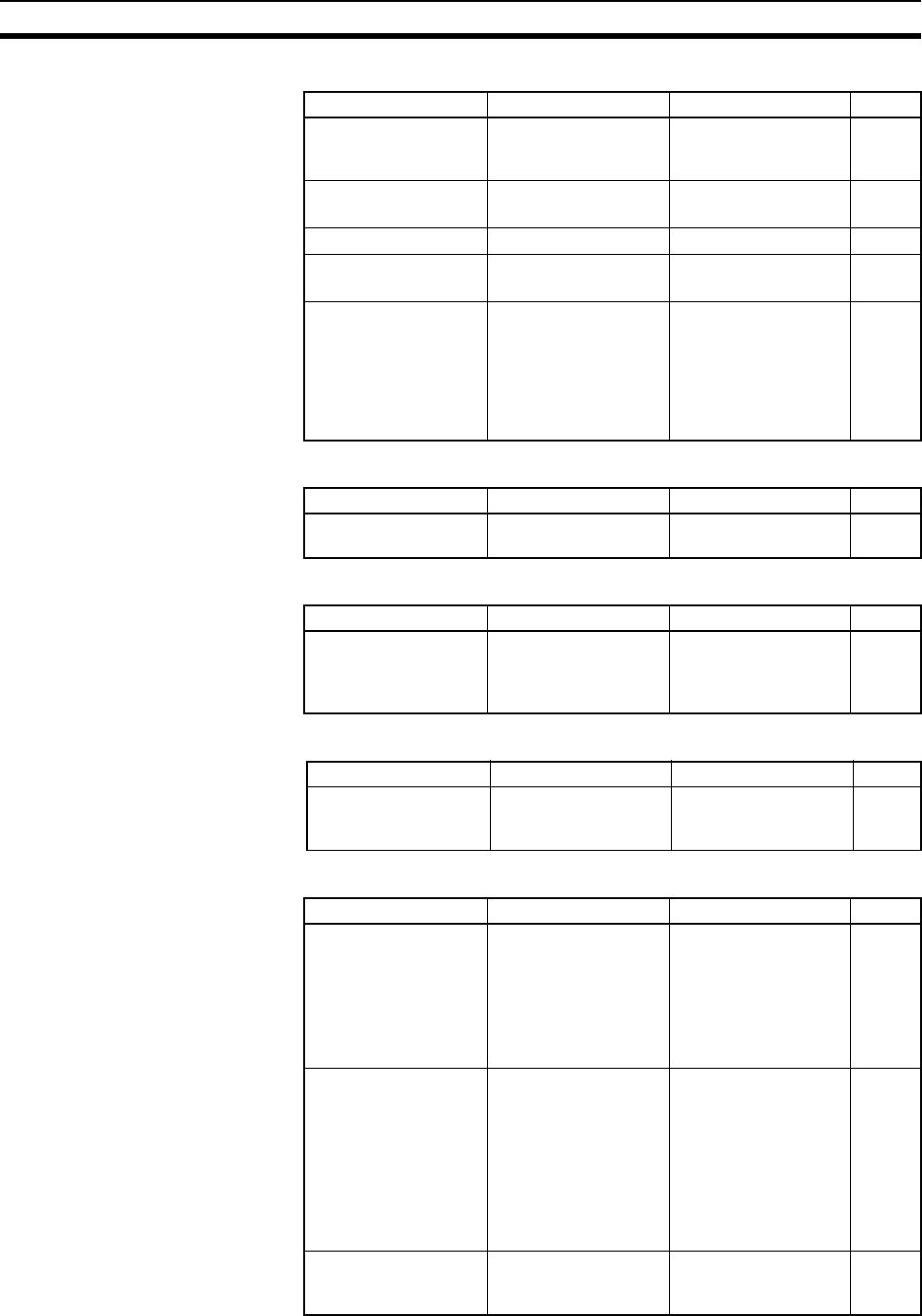
6. Set the data link mode.
Contents Method Nodes Page
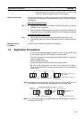
a. Set the unit num-
ber.
Use the front rotary
switches.
CS/CJ-series, CVM1,
and CV-series PLCs
only
98
b. Set the node
address.
Use the front rotary
switches.
All nodes 95, 99
c. Set the baud rate.
Use the DIP switch. All nodes 95, 99
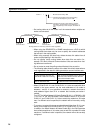
d. Set the operating
level.
Use the DIP switch. C200HX/HG/HE PLCs
only
95
e. Set the terminal
resistance
Use the front switch
for CVM1, CV-series,
CS/CJ-series, and
CQM1H-series PLCs
or the bottom switch
for C200HX/HG/HE
PLCs.
All nodes
End nodes on the net-
work: ON
All other nodes: OFF
96, 99
Contents Method Nodes Page
Turn ON the power to
the PLC.
--- All nodes ---
Contents Method Nodes Page
Connect the Program-
ming Console or Con-
troller Link Support
Software.
Use the special con-
nection cable.
CS/CJ-series, CVM1,
and CV-series PLCs
only
21
Contents Method Nodes Page
Create the I/O tables. Use the Support Soft-
ware or Programming
Console.
CS/CJ-series, CVM1,
and CV-series PLCs
only
---
Contents Method Nodes Page
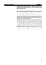
Enable 62 nodes for a
wired network.
Use Support Software
for the PLC or the Pro-
gramming Console.
All nodes
Note: This setting
must be made to con-
struct a network that
uses a node address
higher than 32 (See
note a.)
78
Set data link mode to
manual.
Use Support Software
for the PLC or the Pro-
gramming Console.
(See note b.)
Data link startup node
only
The node that is used
to start the data links
is called the startup
node. It is necessary
to decide beforehand
which node will be the
startup node.
113
Set the data link status
storage format. (CS/
CJ Series only)
Use Support Software
for the PLC or the Pro-
gramming Console.
Data link startup node
only (See note c.)
160