


62
Unit Installation Section 3-2
Note When installing several CS-series CPU Bus Units at the same time, a total of
16 CS-series CPU Bus Units maximum may be installed.
Up to eight CS/CJ-series Controller Link Units with unit version 1.2 or later
can be connected to a single CPU Unit. When connecting multiple Controller
Link Units to the CPU Unit, consider the current consumption of the CPU Unit
and each CPU Bus Unit before selecting the Power Supply Unit. For details on
Controller Link Unit current consumption, refer to
Controller Link Unit Models
and PLCs on page 16
. For details on current consumption of each Unit, refer
to the SYSMAC CS Series Programmable Controllers Operation Manual
(W339).
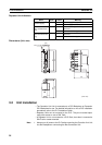
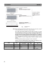
The following table provides an example of current consumption
Example: Using the C200HW-PA204 Power Supply Unit supplying a maxi-
mum current of 4.6 A (5 V) and maximum power of 30 W.
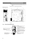
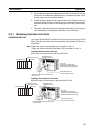
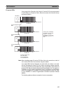
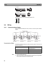
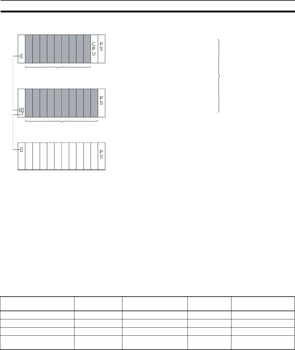
CPU Rack
The Unit can be mounted to the 2/3/5/8/10
slots shown in the diagram on the right.
CPU Backplane
CS1W-BC103, CS1W-BC083, CS1W-BC053, CS1W-BC033, CS1W-BC023
2/3/5/8/10 slots
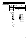
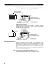
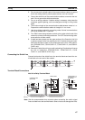
CS Expansion Backplane
CS Expansion Backplane
Slots 3/5/8/10 shown in the illustration can be
used.
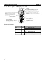
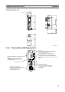
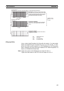
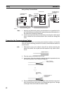
C200H Expansion I/O Backplane
Controller Link Units cannot be mounted to
Expansion I/O slots.
3/5/8/10 slots
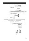
PS: Power Supply Unit
CPU: CPU Unit
CS1W-BI103, CS1W-BI083, CS1W-BI053, CS1W-BI033
C200H Expansion I/O Backplane
Of these slots, installation
is possible in up to 8 slots
(unit Ver. 1.2 or later).
Installation in up to 4 slots
is possible for pre-Ver. 1.2
Units.
Name Model Current consumption
per Unit (A)
Number of
Units
Current consumption
(A)
CPU Backplane (8 slots) CS1W-BC083 0.11 A 1 0.11 A
CPU Unit CS1H-CPU67H 0.82 A 1 0.82 A
Controller Link Unit (Optical) CS1W-CLK21-V1 0.33 A 8 2.64 A
Tot al 3.57 (power consump-
tion: 17.85 W)