


301
Status Area and Troubleshooting Section 9-2
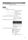
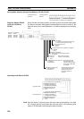
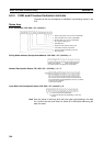
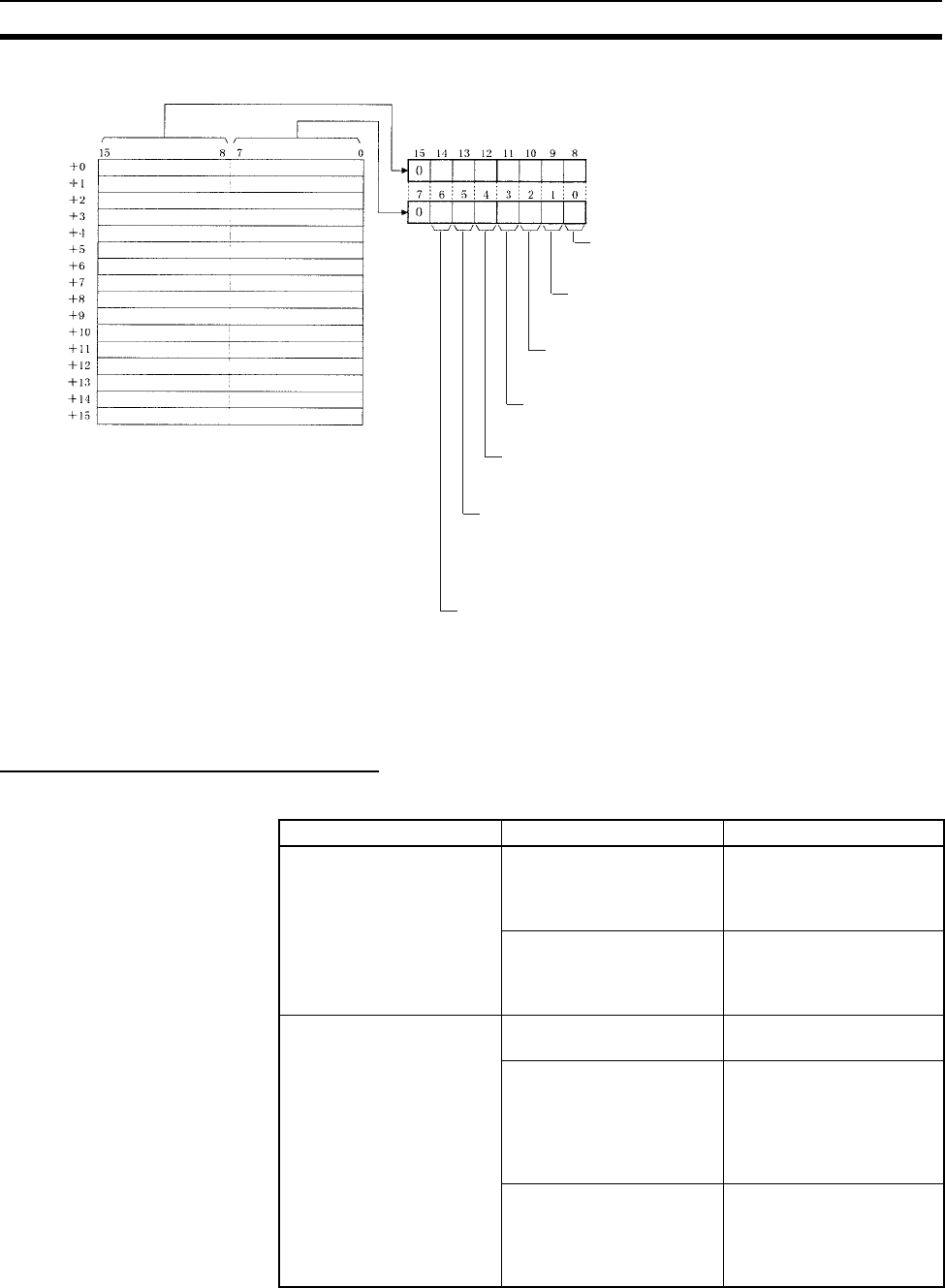
Data Link Status: First Data Link Status Word + 0 to + 15
Note Refer to 5-4 Checking Data Link Status for details on status flags.
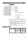
Troubleshooting with Status Flags
Data Link Status
Node 2
Node 4
Node 6
Node 8
Node 10
Node 12
Node 14
Node 16
Node 18
Node 20
Node 22
Node 24
Node 26
Node 28
Node 30
Node 32
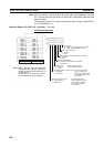
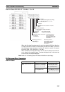
PLC status
0: Inactive (user program not running)
1: Active (user program running)
Communications error (data link reception)
0: Normal
1: Error
PLC's CPU Unit error
0: Normal
1: Error
Data link participation
0: Not in data link or data link inactive
1: In data link
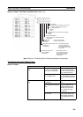
Offset error
0: Normal
1: Error
Error: Offset exceeds
number of send words.
Insufficient (short) receive area
0: Sufficient
1: Insufficient
Insufficient: Receive
area is smaller than
send area. Excess data
is truncated; other data
is received.
Remaining receive area
0: Not remaining
1: Remaining
Remaining: Receive
area is larger than send
area. Data is received
and remaining words
are cleared.
Node 1
Node 3
Node 5
Node 7
Node 9
Node 11
Node 13
Node 15
Node 17
Node 19
Node 21
Node 23
Node 25
Node 27
Node 29
Node 31
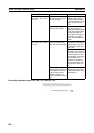
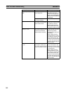
Bit status Probable cause Probable remedy
PLC’s CPU Unit error is 1:
ON
A fatal PLC error, non-fatal
PLC error, or a watchdog
timer error has occurred.
Refer to the PLC’s opera-
tion manual and correct
the error. If the error occurs
again, replace the PLC.
The Unit is mounted to a
non-compatible PLC.
Refer to 1-2-4 Controller
Link Unit Models and PLCs
and mount onto the correct
PLC.
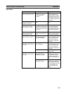
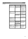
Communications error is 1:
ON
The relevant node is not in
the Network.
Enter the node in the Net-
work.
A communications error
has occurred as a result of
noise.
Conduct an echoback test
using the Controller Link
Support Software and if
this does not correct the
error, check the usage
environment.
A communications error
has occurred.
Refer to page 276 Trouble-
shooting with RUN, ERC,
ERH and INS Indicators
and troubleshoot accord-
ingly.