


190
Using the Message Service Section 6-3
C200HX/HG/HE PLCs
CVM1, and CV-series
PLCs
CQM1H-series PLCs
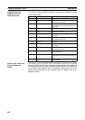
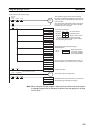
Network Status
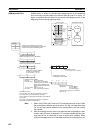
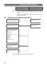
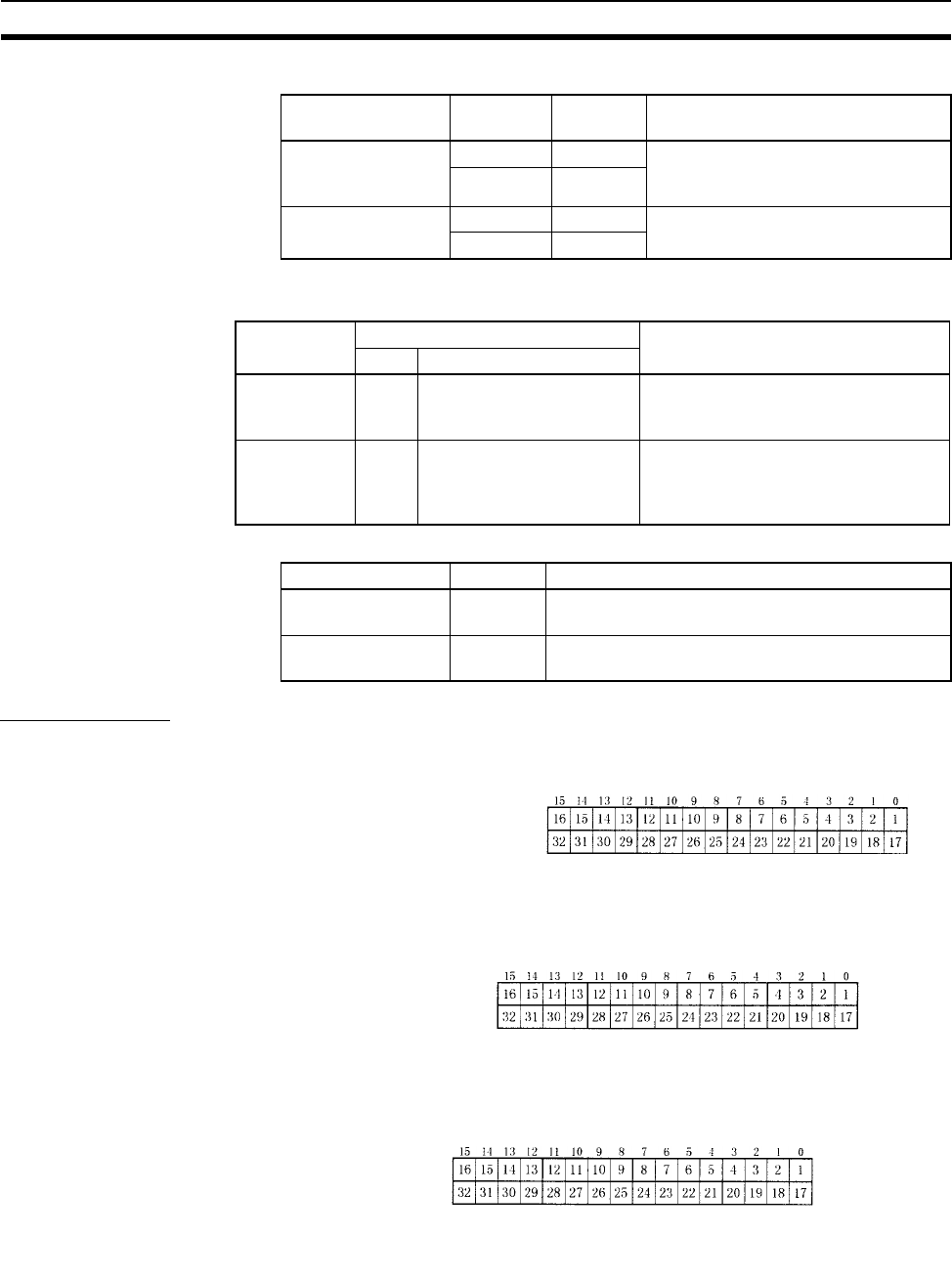
The nodes on the network are shown in the following illustrations.
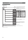
C200HX/HG/HE PLCs
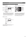
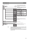
CS/CJ-series, CVM1, and
CV-series PLCs
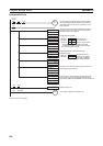
CQM1H-series PLCs
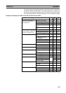
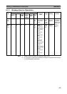
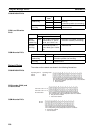
Name Operating
level
Address Contents
Network Instruction
Enabled Flag
1 SR 25204 0: Execution not possible (already
executing)
1: Execution possible (not executing)
0 SR 25201
Network Instruction
Error Flag
1 SR 25203 0: Normal end
1: Abnormal end
0 SR 25200
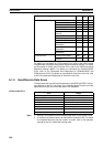
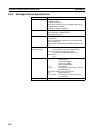
Name Address Contents
Word Bit
Network
Instruction
Enabled Flag
A502 Port number corresponds
to bit number, i.e., port 0:
bit 00, port 1: bit 01, etc.
0: Execution not enabled (executing)
1: Execution enabled (not executing)
Network
Instruction
Error Flag
A502 Port number corresponds
to bit number plus 8, i.e.,
port 0: bit 08, port 1: bit 09,
etc.
0: Normal end
1: Abnormal end
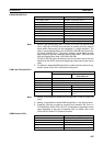
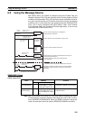
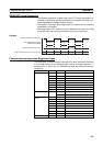
Name Address Contents
Network Instruction
Enabled Flag
AR 0209 0: Execution not possible (already executing)
1: Execution possible (not executing)
Network Instruction
Error Flag
AR 0208 0: Normal end
1: Abnormal end
Operating level 0
AR 08
AR 09
Operating level 1
AR 12
AR 13
The numbers in the squares indicate node addresses.
The corresponding node participation status is as follows:
0: Not part of network
1: Part of network
The numbers in the squares indicate node addresses.
The corresponding node participation status is as follows:
0: Not part of the network
1: Part of the network
N: Unit number
CIO 1500 + 25 × N + 2
CIO 1500 + 25 × N + 3
IR 192
IR 193
The numbers in the squares indicate node addresses.
The corresponding node participation status is as follows:
0: Not part of network
1: Part of network