


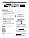
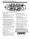
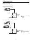

q DC IN socket (XLR 4P)
DC power input socket.
The AC adaptor AJ-B75 (optional accessory) must be
used to supply the power. The unit’s operation cannot be
guaranteed if any other power supply is used instead.
w VIDEO IN connector (BNC)
The analog composite signal is supplied to this connector.
e VIDEO/Y OUT connector (BNC) (VTR2 only)
The analog composite signals are output from this con-
nector.
The Y (luminance) signal is output when CMPNT has
been set for set-up menu item No.806 (V OUT SEL).
r PB VIDEO/Y OUT connector (BNC) (VTR1 only)
The analog composite signals are output from this con-
nector during playback only (E-E signals are not output).
The Y (luminance) signal is output during playback only
when CMPNT has been set for set-up menu item No.806
(V OUT SEL). (E-E signals are not output).
t VIDEO MON OUT/TC OUT connector (BNC)
The video monitor signals are output from this connector.
The time code signal is output when TCOUT1 or TCOUT2
has been set for set-up menu item No.514 (TC OUT).
y REMOTE connector (D-SUB, 9P, female)
This is the RS-422A interface remote connector. It
enables the unit to be operated from an external con-
troller. The VTR1 remote connector is switched to a
REMOTE OUT connector by setting the CONTROL
switch on the keyboard to EXT VTR so that an external
VTR can be controlled using the VTR1 controls on this
unit.
u AUDIO IN connectors (CH1/CH2) (XLR ×2)
The analog audio signals are supplied to these connec-
tors.
i CH2 INPUT level switch
Used to select the analog audio input signal CH2 level.
LINE: Line input (+4/0/–20 dBu)
MIC: MIC input (–50 dBu)
o AUDIO OUT connectors (CH1/CH2) (XLR ×2) (for VTR2
only)
Analog audio signals are output from these connectors.
!0 PB AUDIO OUT connectors (CH1/CH2) (XLR ×2) (for
VTR1 only)
The analog audio signals are output from these connectors
only during playback. (The E-E signals are not output.)
!1 AUDIO MON OUT connector (XLR)
The audio monitor signal is output from this connector.
!2 REF VIDEO IN/TC IN connectors (BNC ×2)
Analog composite signals are supplied to these connec-
tors.
These are loop-through connectors provided with auto-
matic 75-ohm termination.
!3 REF THRU/TC IN selector switch
This selects whether the right-hand REF VIDEO IN/TC IN
connector !2 is to be used as the REF loop-through con-
nector or as the TC input connector.
• REF THRU: The connector is used as the REF loop-
through connector. 75-ohm termination is provided auto-
matically.
• TC IN: The connector is used as the time code input
connector. The left-hand REF VIDEO IN connector !2
still serves as the REF input while the loop-through
function is canceled, and the 75-ohm termination is fixed
at ON.
!4 VIDEO OUT connector (P
B OUT/PR OUT) (BNC)
The P
B and PR signals among the analog component sig-
nals are output from this connector.
!5 PB VIDEO OUT connector (P
B OUT/PR OUT) (BNC)
The P
B and PR signals among the analog component sig-
nals are output from this connector during playback only.
!6 EDL connector (D-SUB, 9P, male)
This is used to connect to a personal computer, etc. to
download and/or upload the edit list data.
It is also used to connect the audio memory unit which is
available as an optional accessory.
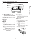
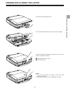
Before carrying the main unit, be sure to attach the accessory
connector cover.
Do not turn on the unit’s power with the connector cover
attached.
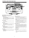
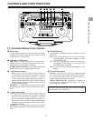
CONTROLS AND THEIR FUNCTIONS
14
DC IN
VIDEO IN
VIDEO/Y
P
B
EDL
VIDEO OUT
AUDIO IN
CH 1
V
T
R
2
V
T
R
2
CH 1
CH 2
P
R
REMOTE
PB VIDEO OUT
AUDIO OUT
AUDIO MON OUT
AUDIO MON OUT
VIDEO MON /TC OUT
CH 1
CH 2
MIC
LINE
VIDEO IN
VIDEO/Y
P
B
AUDIO IN
AUDIO OUT
VIDEO MON /TC OUT
TC IN
REF IN
REF
THROUGH
75ΩAUTO
CH 1
V
T
R
1
V
T
R
1
CH 2
CH 2
P
R
REMOTE
1
2
2ry 5
9q7
6456
q8
we3
07
t
DC IN
VIDEO IN
VIDEO/Y
P
B
EDL
VIDEO OUT
AUDIO IN
CH 1
V
T
R
2
V
T
R
2
CH 1
CH 2
P
R
REMOTE
PB VIDEO OUT
AUDIO OUT
AUDIO MON OUT
AUDIO MON OUT
VIDEO MON /TC OUT
CH 1
CH 2
MIC
LINE
VIDEO IN
VIDEO/Y
P
B
AUDIO IN
AUDIO OUT
VIDEO MON /TC OUT
TC IN
REF IN
REF
THROUGH
75ΩAUTO
CH 1
V
T
R
1
V
T
R
1
CH 2
CH 2
P
R
REMOTE
Connector Section (for both VTR1 and VTR2)