


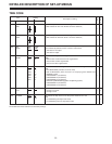
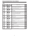
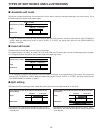

AUDIO
Item Setting
Description of setting
No. Item No. Item
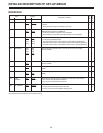
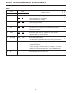
707 DV 0000 ST1
OUTPUT 0001 ST2
0002 ST1+2 ™™
708 PB FADE 0000 AUTO
0001 CUT
0002 FADE ™™
709 AUDIO 0000 PCM
SLOW 0001 CUE
0002 A-CUE
™™
710 SHTL 0000 OFF
AUDIO 0001 CUE
™™
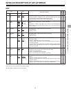
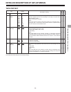
711 AUTO 0000 V1+V2
MONI 0001 AUTO
™
712 DV PB 0000 OFF
ATT 0001 ON ™™
713 CH1 REC SEL 0000 CH1
0001 CH2
0002 MIX
™
714 CH2 REC SEL 0000 CH1
0001 CH2
0002 MIX
™
The underlined number and item are the factory settings.
DETAILED DESCRIPTION OF SET-UP MENUS
34
This selects the audio CH1 and CH2 outputs during DV format playback.
0: The CH1 track is output for CH1 and CH2 track for CH2.
1: The CH3 track is output for CH1 and CH4 track for CH2.
2: The CH1 and CH3 tracks are mixed and output to CH1, and the CH2 and
CH4 tracks are mixed and output to CH2.
This selects how the audio edit points (IN, OUT) are to be processed during
playback.
0: Processing accords with status during recording.
1: Forced cut editing
2: Forced fade editing
This sets the audio output mode during slow playback.
0: PCM mode: the PCM audio signals are output between –0.43 and +1, and
the CUE audio signals are output at other speeds.
1: CUE mode: the PCM audio signals are output at the FWD ×1 speed; the
cue audio signals are output at any other speed.
2: ALL CUE mode: the cue audio signals are output at all speeds including
the FWD ×1 speed.
This selects whether the cue audio is to be output to LINE OUT in the shuttle
mode.
0: Cue audio is not output.
1: Cue audio is output.
This selects the signal to be output to the speaker/headphone.
0: Processing accords with the SPEAKER/HEADPHONES switch.
1: The signal of the VTR operated last is output.
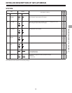
<Notes>
• If the OPERATION MODE switch set to the “SEPARATE” position, output is
fixed at “V1 + V2.”
• If the CONTROL switch set to the “REMOTE” or “EXT VTR” position, output
is fixed at “V1 + V2.”
This selects the output level while a DV tape is being played back.
OFF: Output level is not reduced.
ON: Output level is reduced.
This selects the signals to be recorded on CH1.
0: CH1 input
1: CH2 input
2: CH1 input and CH2 input mixed signals
This selects the signals to be recorded on CH2.
0: CH1 input
1: CH2 input
2: CH1 input and CH2 input mixed signals
VV
TT
RR
12