


DETAILED DESCRIPTION OF SET-UP MENUS
31
VV
TT
RR
12
Detailed description of set-up menus
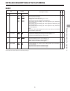
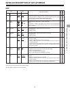
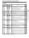
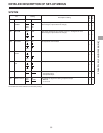
TIME CODE
Item Setting
Description of setting
No. Item No. Item
507 TC MODE 0000 P-REC
0001 P-FREE
0002 I-REG
0003 E-VITC
™™
0004 E-LTC
0005 VTR1 TC*
508 TC
PRESET
™™
509 UB
PRESET
™™
510 REGEN 0000 AS&IN
MODE 0001 ASSEM
™
0002 INSRT
0003 SW
511 TC JUMP 0000 OFF
0001 VTR1
™
0002 VTR2
0003 ALL
512 PHASE CORR 0000 OFF
0001 ON
™™
513 V-MON/ 0000 V-MON
TC OUT 0001 TCOUT1
0002 TCOUT2*
™™
*The VTR1 TC and TCOUT2 settings can be performed only for VTR2.
This selects whether the time code generated by the internal TCG or an
external time code is to be used.
0: Internal TC is set to PRESET and used in the REC RUN mode.
1: Internal TC is set to PRESET and used in the FREE RUN mode.
2: Internal TC is used in the REGEN mode.
3: VITC of input video signals is used in the REGEN mode.
4: Time code input LTC is used in the REGEN mode.
5: The time code of the sub-code is used in the REGEN mode when the
OPERATION MODE switch is in the INT mode.
This sets the TCG (time code generator) value.
00:00:00:00 to 23:59:59:29
This sets the user bit value.
00 00 00 00 to FF FF FF FF
Regardless of the set-up menu No. 507 (TC MODE) setting, this sets the
I-REGEN mode during assemble editing and/or time code (TC) insert editing
(TC rewrite mode).
0: The I-REGEN operation is performed during assemble editing and insert
editing.
1: The I-REGEN operation is performed during assemble editing.
2: The I-REGEN operation is performed during insert editing.
3: The I-REGEN operation accords with the set-up menu No. 507 (TC MODE)
setting.
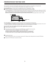
This sets whether TC JUMP is to be enabled.
0: TC JUMP is disabled.
1: TC JUMP is enabled for VTR1 only.
2: TC JUMP is enabled for VTR2 only.
3: TC JUMP is enabled for both VTR1 and VTR2.
<Note>
When TC JUMP is enabled, the tape is first cued up to the IN point and, using
this IN point as a reference, preroll and the approach are then conducted.
The TC reference is selected as soon as the IN point is passed and editing
and recording are initiated.
This selects whether the phase compensation of LTC generated by TCG is to
be controlled.
0: The phase compensation is not controlled.
1: The phase compensation is controlled.
This selects whether the video monitor output connector is to be used as the
TC output connector.
When it is used as the TC output connector, align the phase of the TC signal
which is output in the E-E mode with the phase of the video output or input
TC signal.
0: The connector is used as the video monitor output connector.
1: The connector is used as the TC output connector, and in the E-E mode
the phase of the TC signal which is output is aligned with the phase of the
input TC signal.
2: The connector is used as the TC output connector, and in the E-E mode
the phase of the TC signal which is output is aligned with the phase of the
video output signal.