


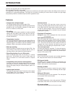
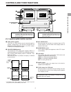
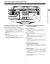
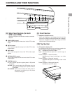
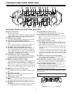
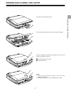
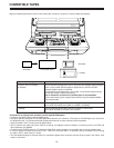
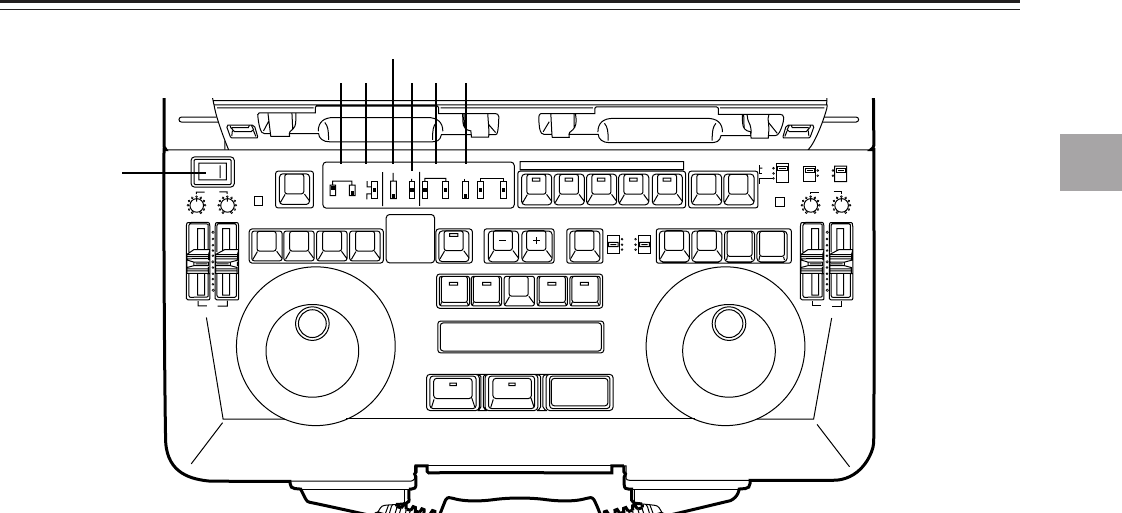
[3] Front Keyboard Switches
q POWER switch
w REC INHIBIT switch
ON: For inhibiting recording.
OFF: Recording is possible at this position.
Recording with VTR1 is possible only when the
OPERATION MODE switch has been set to SEPA-
RATE.
e CONTROL switch
REMOTE: For controlling the laptop from the external
REMOTE connector (9P).
LOCAL: For controlling the laptop using the controls
on the laptop’s front panel.
EXT VTR: For controlling an external VTR from the
unit’s front panel.
It enables the VTR connected to the 9-pin
connector on the VTR1 side to be operated
by the control buttons of VTR1.
r PREROLL switch
This sets the preroll time to 3, 5 or 7 seconds.
When it is not possible to achieve synchronization, the
preroll time is incremented by one setting. At the 7-sec-
ond setting, the time remains at 7 seconds even if syn-
chronization is lost.
t SYNCHRO switch
This sets whether synchronization and/or color framing
are to be performed.
CF: Both synchronization and color framing are per-
formed.
ON: Synchronization is performed but color framing is
not performed.
OFF: Synchronization is not performed.
y AUDIO MONITOR switch (for both VTR1 and VTR2)
CH1: The CH1 sound is output.
MIX: The sounds of CH1 and CH2 are mixed and output.
CH2: The CH2 sound is output.
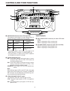
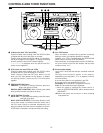
u SPEAKER/HEADPHONES switch
This selects the sound which is output from the speaker
or headphones.
V1:
V1•V2:
V2:
• This is valid only when set-up menu item No.711 (AUTO
MONI) has been set to “V1+V2.” When set-up menu
item No.711 (AUTO MONI) has been set to “AUTO,” the
sound of the VTR operated last is automatically output
regardless of the switch position.
• When V1+V2 is selected, and editing or dubbing is per-
formed from VTR1 to VTR2, the sound may be accom-
panied by an echo effect: this is normal and not indica-
tive of malfunctioning. If this effect is unpleasant, select
V1 or V2, or set AUDIO MONI on the above item to
“AUTO.”
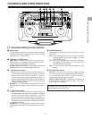
CONTROLS AND THEIR FUNCTIONS
7
Controls and their functions
-
-
-
-
-
-
-
-
-
-
-
-
-
-
-
-
-
-
-
-
-
-
-
-
-
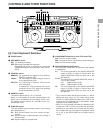
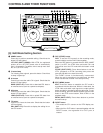
EJECT
VTR1
POWER
REC
CH1
RESET
REC
DIAG
REMOTE
EXT VTR
LOCAL-
VTR1 VTR2
CONTROL
ON
OFF
REC
INHIBIT
OFF
ON
CH2
PB
AUDIO LEVEL
REW
FF
STOP
STB OFF
TRACK
PLAY STILL
1ST EDIT
BS
EVENT
SPLIT
ASMBL
IN OUT
VTR1 VTR2 VTR1 VTR2
PREROLL
SYNCHRO
7
5
3
CF
ON
OFF
CH1
MIX
CH2
V1
V1•2
V2
SWAP
NORM
MIX
AUDIO
MONITOR
SPEAKER/
HEADPHONES
AUDIO
SWAP
DUMP LOAD
EDL
CLEAR
FS
RECALL
LAST
EDIT
VA1A2TC
PLAY
IN OUT
GO TO
ENTRY / SHIFT
EDIT MODE
COUNTER
CTL
TC
UB
VTR1
EJECT
VTR2
RESET
REC
STORE
STOP
STB OFF
MENU
EDIT
STILL
REW
FF
VTR2
REC
CH1 CH2
OPERATION MODE
VTR2 AUDIO
INPUT SELECT
EDIT
INT
EXT
SEPARATE
CH1 CH2
VTR1
EXT
PB
AUDIO LEVEL
PREVIEW
REVIEW MULTI
AUTO EDIT
ALL STOP
1
2
3 6 7
4
5
The sound selected by the AUDIO MONITOR
switch of VTR1 is output (in stereo when the
AUDIO MONITOR switch has been set to the
MIX position).
The sound by the AUDIO MONITOR switch of
VTR1/VTR2 is output.
Left: Output sound of VTR1
Right: Output sound of VTR2
The sound selected by the AUDIO MONITOR
switch of VTR2 is output (in stereo when the
AUDIO MONITOR switch has been set to the
MIX position).