STATUS
RX OK
TX OK
TEST
STANDBY
DATACOM
PARADISE
Tx path OK for 3.7days
Rx path OK for 2.1days BER < 1E-12
0
1 2
3
4
5 6
7
9
8
YES /
ENTER
NO /
PREV
MAIN
P300 Series
Satellite Modem
STATUS
RX OK
TX OK
TEST
STANDBY
Status LEDs
Green:
Red:
Green:
Off:
Green:
Off:
Off:
Amber:
Off:
Amber:
Modem itself OK
Modem internal fault
Rx traffic OK
Rx traffic fault (external to modem
)fic fault (external to modem)
Tx traffic OK
Tx traffic fault (external to modem
)fic fault (external to modem)
Normal
Loopback or Test mode active
Normal (Tx carrier on)
Tx carrier off or Standby of 1:1
P300H P300 Series Modem Installation and Operating Handbook Page 17
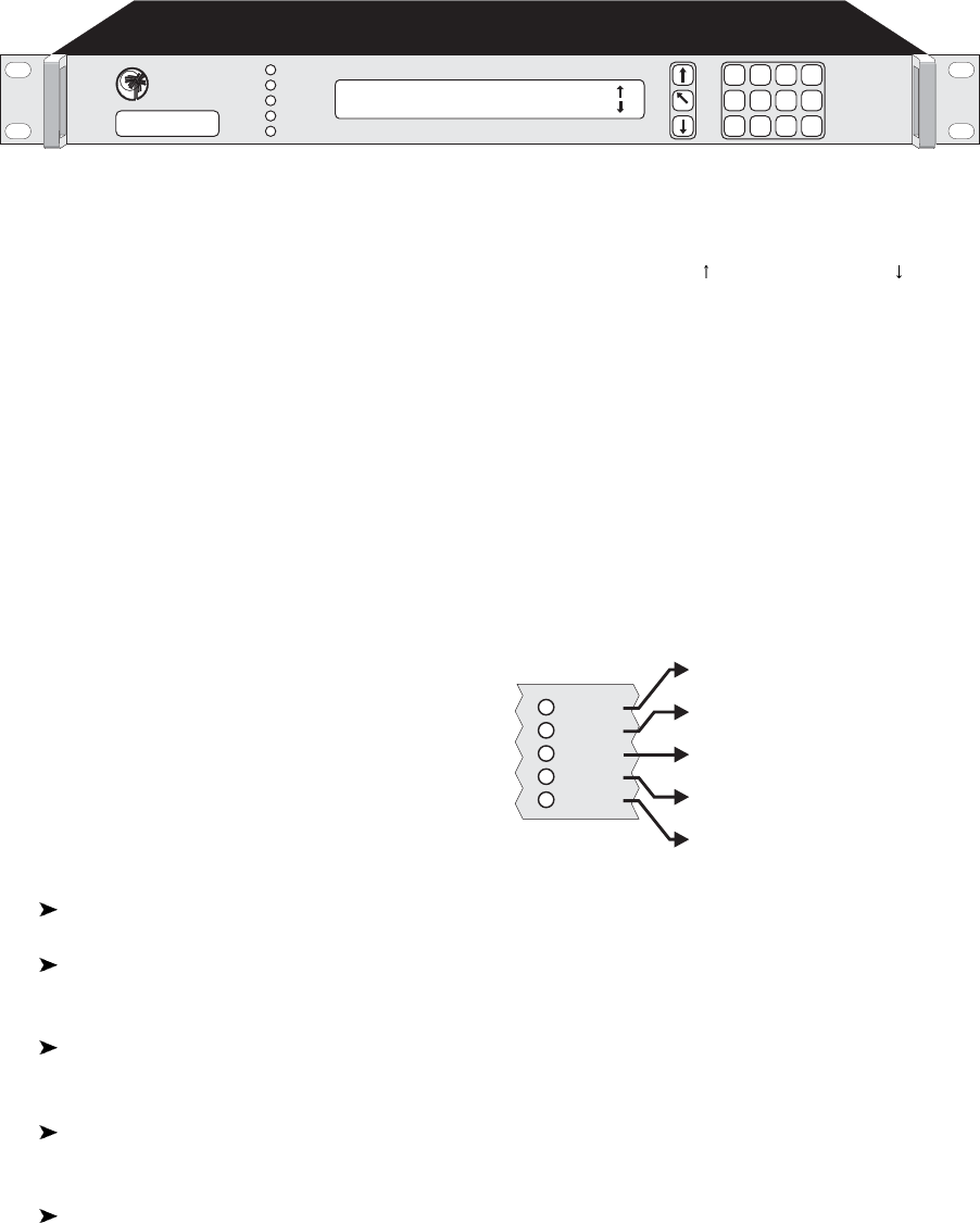
P300 Modem front panel view
3.4 FRONT PANEL FEATURES
Keyboard
The keyboard is of the membrane type (an integral part of the front panel) which provide a direct tactile feel.
There are 15 keys in total - number keys in the range 0 to 9, an up arrow key (
), down arrow key ( ), MAIN
key, YES/ENTER key, and NO/PREV key.
LCD display
This backlit display provides 2 lines of 40 characters each and is highly legible even in conditions of high
ambient light. The LCD provides detailed information about the status and configuration of the unit, and
when appropriate, prompts the user to enter data via the keypad.
Monitor port
The circular monitor port available on the front panel of previous products has been moved to the rear
panel and is now combined onto the Async ESC connector (a `D` type connector instead of the difficult to
obtain 8 pin `din` audio type connector). See the description of the “Async ESC connector” under the rear
panel description which starts on the next page.
LED Indicators
Five LEDs on the front panel provide summary fault
information, so that even when the LCD is unavailable
for status display (such as when the operator is
reconfiguring the unit, and a menu is displayed), the
current status can always be assessed. If any of the
LED's indicate a fault, press MAIN, then select Status
to display the current fault condition.
In normal operation there should be three GREEN LED's showing.
If the Status is RED, the unit has failed due to internal or possibly external conditions. Refer to
the text on the LCD Status screen and rectify if possible.
If the TX OK or RX OK LED's are off, then the Tx or Rx traffic has failed due to an external fault,
again refer to the text on the LCD Status screen and rectify if possible.
If the TEST LED is AMBER, a test mode or loopback is active, press MAIN, and select Test to
query or change the test settings.
If the STANDBY LED is Amber, the Tx carrier is off. It may be intentionally switched off, or it may
be muted due to either a fault, an external mute signal, or if in a 1-FOR-1 redundant pair it may be
the standby unit.


