IN-1
7610-A2-GB20-10 November 1997
Index
Numbers
511 test pattern, 7-4– 7-5
A
access
effective level, 4-4
SNMP, 1-4, 4-6
to the ATI, 4-1– 4-5
administer login, 4-2
alarm
condition, 7-1
LED, 6-2
messages, 8-1– 8-3
alarms & traps, options, A-1, A-20– A-22
alternate directory, 3-5– 3-7
ASCII
alarm, 7-1
alarm messages, 3-5, 8-1
characters, 3-1, A-29– A-30
async terminal interface.
See
ATI
ATI
access, 4-4
initiating, 2-1– 2-8
management, 1-1
monitoring, 6-1
C
cables, rear panel, E-1– E-5
cables to order.
See
Start-Up Instructions
call, setup, 3-5– 3-7
communication protocol options, A-1, A-22
community names, for SNMP, 4-6
configuration
menu, 2-2– 2-3
option areas, 3-3– 3-4
option tables, A-1– A-26
option worksheets, B-1– B-4
configuration examples, 1-3
connectors, rear panel, E-1– E-5
control, menu, 2-2– 2-3
create login ID, 4-2
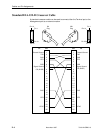
crossover EIA-232 cable, E-4
CTS, clear to send LED, 6-4
customer, configuration areas, 3-3
D
data port.
See
DTE
data port options, A-1, A-9– A-11
data port tests, 7-4
defaults
configuration option, 3-3– 3-4
reload factory, 7-7
device
messages, 8-4– 8-5
name, 3-1
reset, 7-7
dial-in
external device access, 4-1– 4-5
NMS management, 3-5
dialing out, SNMP traps, 8-3
directory, call, 3-5– 3-7
displaying, configuration options, 3-4
DM, data mode LED, 6-3
DTE test, 7-4
DTR, data terminal ready LED, 6-4
E
effective access, to ATI, 2-3, 4-4
EIA-232 pin assignments, E-2– E-4
enterprise
MIB objects, C-2, C-18– C-19
SNMP traps, D-3– D-4
external device
access, 4-1– 4-5
options, A-1, A-15


