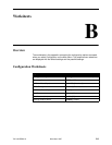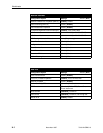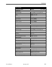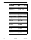
Configuration Option Tables
A-27
7610-A2-GB20-10
November 1997
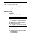
SNMP Traps Options
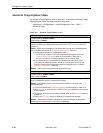
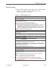
To access the SNMP Traps Options screen, follow this menu selection sequence:
Main Menu
→
Configuration
→
Load Configuration From
→
Edit
→
SNMP & Communication
→
SNMP Traps
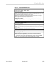
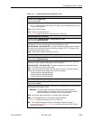
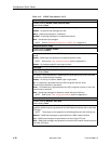
Table A-12. SNMP Traps Options (1 of 2)
SNMP Traps
Possible Settings: Enable, Disable
Default Setting: Disable
Controls the generation of SNMP trap messages. The options for addresses and types
of traps are located in this table.
H SNMP Management must be enabled in Table A-10.
Enable – SNMP trap messages are sent out to SNMP managers.
H If the destination is the Management port and an external device is attached to the
Management port, the messages are sent immediately if there is an active
connection. Automatic call initiation is based on the Alarm & Trap Dial-Out option
in Table A-8. The destination is set with the Trap Manager Destination option.
Disable – No SNMP trap messages are sent out.
Number of Trap Managers
Possible Settings: 1, 2, 3, 4, 5, 6
Default Setting: 1
Sets the number of SNMP management systems that will receive SNMP traps.
1 to 6 – Number of trap managers. An NMS IP address is required for each manager.
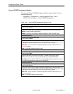
Trap Manager “
n
” IP Address
Possible Settings: 000.000.000.000 – 223.255.255.255, Clear
Default Setting: 000.000.000.000
Specifies the Internet Protocol address used to identify each SNMP trap manager.
“
n
” represents the number of the manager (from 1 to 6).
000.000.000.000 – 223.255.255.255 – Enter an address for each SNMP trap manager.
The range for the first byte is 000 to 223, with the exception of 127. The range for the
remaining three bytes is 000 to 255.
Clear – Clears the IP address and sets to all zeros.
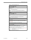
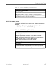
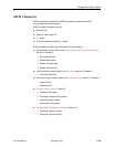
Trap Manager “
n
” Destination
Possible Settings: Default, Mgmt, IMC
Default Setting: Default
Provides the network destination path of each trap manager. “
n
” is the number of the
manager (from 1 to 6).
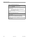
Default – Uses the address set in the Default Network Destination in Table A-9.
Mgmt – The Management port is the network destination.
H Port Use option must be set to Net Link in Table A-5.
IMC – The In-Band Management Channel is the default network destination.
H In-Band Management Channel Rate(bps) option must be set to 1600, 4000, or
8000 bps in Table A-2.


