


2. Installation
8620-A2-GN20-40 July 2003
2-3
Unpacking the Hardware
Carefully remove the 8620 chassis from its shipping container and check for
physical damage. If the 8620 chassis shows signs of shipping damage, report this
immediately to your shipping and sales representatives.
Package Contents
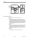
The Hotwire 8620 GranDSLAM chassis, as shipped, consists of the following:
n Four filler plates installed in Slots A, 1, 2, and 3.
n One SIM card installed in bottom slot.
n One AC power cord (if your chassis has the AC power option)
n Two sets of mounting brackets for 19-inch (48.3 cm) and 23-inch (58.4 cm)
rack mounting
n Associated hardware bundled in a plastic bag:
— Set of four rubber feet for desktop mounting
— Four #10-32 mounting screws for mounting in a rack or cabinet
— Four #12-24 mounting screws and four #12-24 self-retaining nuts (for use
with racks without threaded mounting holes)
— Four #8-32 Phillips flat-head screws for mounting the 19-inch or 23-inch
brackets
— Four cable ties to attach the Tip and Ring cables to DSL cards (should
locking pivot brackets not be used)
n Additional plastic bag with the following to connect Tip and Ring cables to DSL
cards:
— Four locking pivot brackets
— Four #4-40 Phillips pan-head, captive screws (to replace longer captive
screws when using the rear-mounted connectors)
n For normal functionality, the Hotwire 8620 GranDSLAM chassis requires:
— An SCP card, or an MCP card and an SCM card
— At least one DSL card
Be sure to register your warranty at www.paradyne.com/warranty.