


2. Installation
2-10 July 2003 8620-A2-GN20-40
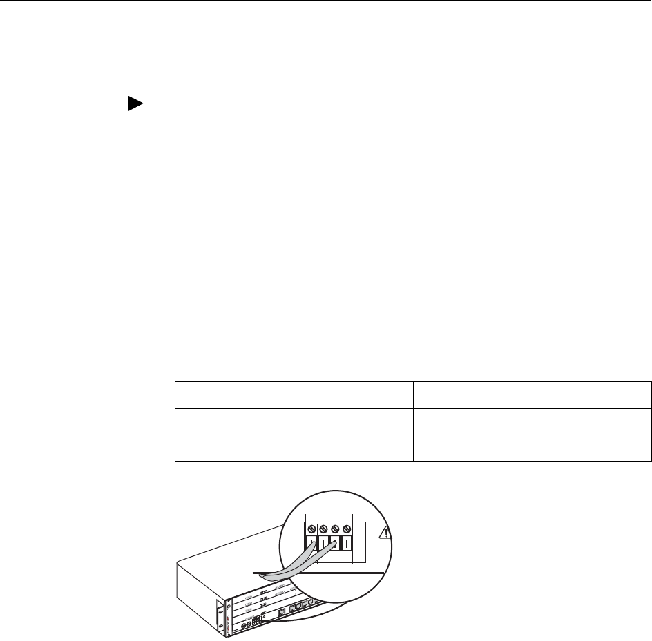
Using a Single DC Power Source
Procedure
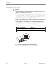
✔ Make sure that the DC power source wires are not powered (that is, the circuit
breakers or fuses are open at the source).
✔ The ends of the power source wires (14–18 AWG or 2.5 mm
2
solid or stranded
wire) must be stripped of insulation. If the wires are not stripped, strip the tip of
each wire (about 1/2 inch or 13 mm in length) before inserting the wire into the
appropriate terminal on the –48V input terminal block.
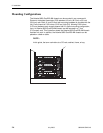
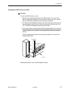
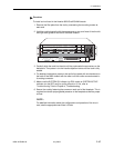
To supply 48 VDC power to the 8620 chassis from a single 48 VDC power source:
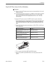
1. Insert the following wires into Terminal A and securely fasten each wire by
tightening the screw above it. The insulation should be fully within the terminal
block and no bare wire should be exposed outside of the block.
2. Clearly label these power source wires as –48V and RTN respectively.
3. Turn on power to the Hotwire 8620 GranDSLAM chassis.
4. Make sure the PWR A LED on the front panel is ON (green).
Insert Power Source A’s . . . Into the . . .
Negative side of the power source –48V A input terminal.
Positive side of the power source RTN A (return) terminal.
MCP
8000
S
Y
S
T
E
M
O
K
A
lrm
T
est
TX
R
X
C
o
ll
E
T
H
E
R
N
E
T
GranDSLAM
8620
E
S
D
S
IM
A
1
2
3
A
C
O
U
T
L
E
T
D
C
F
U
S
E
S
A
B
-
4
8
V
R
T
N
A
B
A
B
AB
D
C
P
O
W
E
R
F
A
N
M
A
J
O
R
M
I
N
O
R
A
L
A
R
M
S
A
L
A
R
M
C
L
O
C
K
A
B
S
E
R
I
A
L
S
C
M
M
C
P
L
A
N
S
C
M
M
C
P
SIM
IP
MVL
8314
S
Y
S
T
E
M
O
K
A
lrm
T
e
s
t
T
X
R
X
L
O
C
1
2
3
4
A
T
M
B
U
S
D
S
L
P
O
R
T
5
6
7
8
9
1
0
1
1
1
2
SCM-E3
10/100BT
8025
S
Y
S
T
E
M
O
K
A
lr
m
T
e
s
t
T
X
R
X
C
o
ll
E
T
H
E
R
N
E
T
U
p
li
n
k
A
lr
m
TX
RX
IP
MVL
8314
S
Y
S
T
E
M
O
K
A
lrm
T
e
s
t
T
X
R
X
L
O
C
1
2
3
4
A
T
M
B
U
S
D
S
L
P
O
R
T
5
6
7
8
9
1
0
1
1
1
2
00-16895
-48V RTN
ABAB