


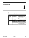


4. Troubleshooting
8620-A2-GN20-40 July 2003
4-3
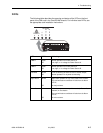
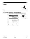
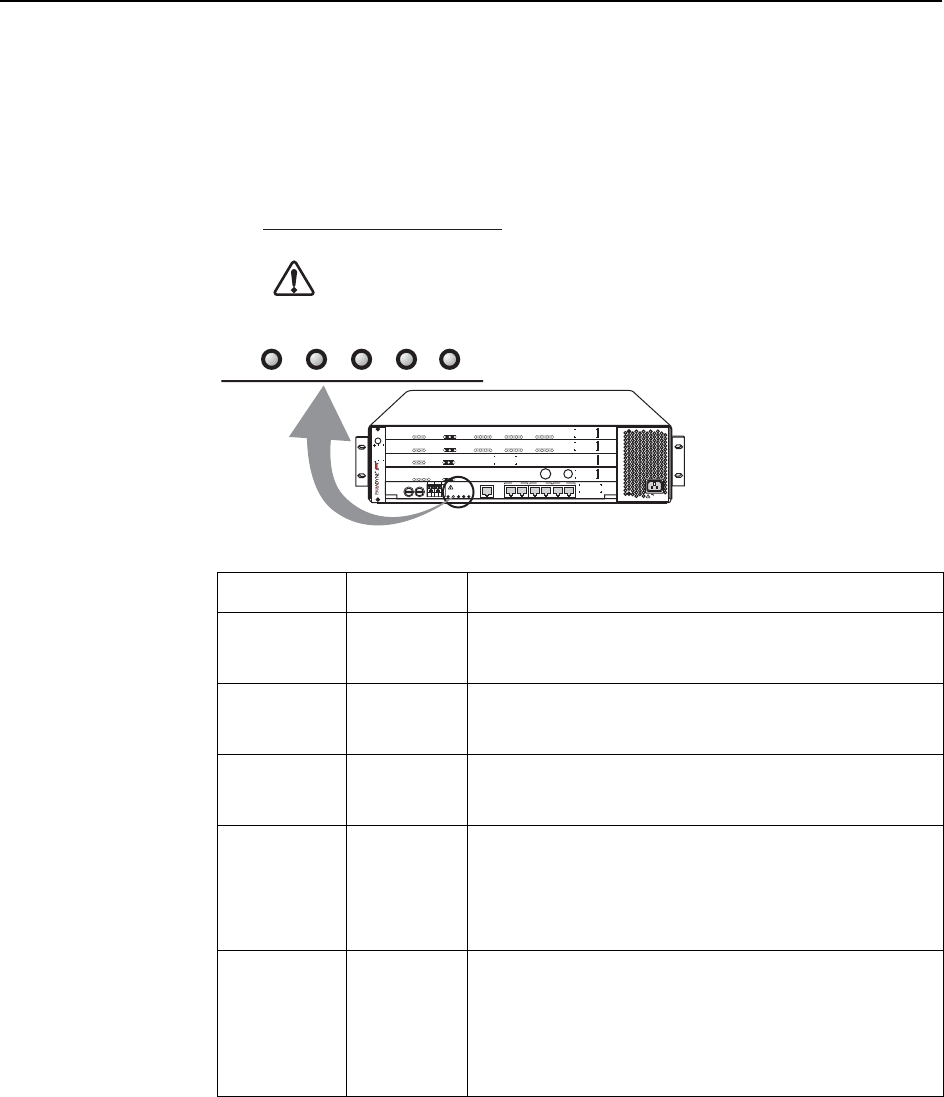
LEDs
The following table describes the meaning and states of the LEDs on the front
panel of the SIM card in the GranDSLAM chassis. For individual card LEDs, see
the appropriate card Installation Instructions.
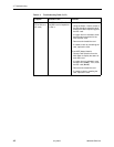
LED LED is . . . Indicating . . .
PWR A Green
Off
Normal operation for Power Source A.
Low, high, or no voltage for Power Source A.
PWR B Green
Off
Normal operation for Power Source B.
Low, high, or no voltage for Power Source B.
FAN ALM Yellow
Off
Fans are working at less than 50% of normal output.
Normal operation or no power to mounting.
Major Alarm Yellow
Off
Major alarm present on any of the cards in the chassis.
The card with alarm conditions will also have its Alarm
LED lit.
No major alarms.
Minor Alarm Yellow
Off
Minor alarm present on any of the cards (or Power Alarm
problem) in the chassis.
The card with alarm conditions will also have its Alarm
LED lit.
No minor alarms.
MCP
8000
SYSTEM
OK
Alrm
Test
TX
RX
Coll
ETHERNET
GranDSLAM
8620
ESD
SIM
A
1
2
3
DC FUSES
A
B
-48V RTN
ABAB
AB
DC
POWER
F
A
N
M
A
J
O
R
M
I
N
O
R
ALARMS
ALARM
CLOCK
AB
SERIAL
SCM MCP
LAN
SCM MCP
SIM
IP
MVL
8314
SYSTEM
OK
Alrm
Tes t
TX
RX
LOC
1
2
3
4
ATM BU S
DSL PORT
5
6
7
8
9
10
11
12
SCM-E3
10/100BT
8025
SYSTEM
OK
Alrm
Test
TX
RX
Coll
ETHERNET
Uplink Alrm
TX
RX
IP
MVL
8314
SYSTEM
OK
Alrm
Test
TX
RX
LOC
1
2
3
4
ATM BU S
DSL PORT
5
6
7
8
9
10
11
12
AC INPUT
02-17239
AB
DC
POWER
F
A
N
M
A
J
O
R
M
I
N
O
R
ALARMS