


25
26
CAS MF Setting: Disabled
(default)
Options: Enabled, Disabled
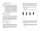
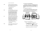
CAS MF: CAS multiframe uses Timeslot 16 (TS16) to send multi-
frame (MF) alignment data. In CAS MF, a MF is defined as 16
frames, where a frame consists of 32 64kb/s timeslots, num-
bered 0 to 31. TS16 of the first frame in the MF contains the
CAS MF alignment word in the upper four bits. The alignment
word is always 0000 (binary). The 2715 does not perform any
signaling in TS16 other than to insert the MF alignment word,
in order to maintain MF alignment. When CAS MF disabled,
the unit transmits user data in TS16; therefore, up to 31 chan-
nels are available for user data. When it is enabled, TS16 is
not available to the user. In this case, the user can use up to
30 channels for data. CAS MF can be used with CRC-4 MF or
by itself. When enabled, both units must employ CAS MF; if
one unit is set for CAS MF, and the other is not, the one using
CAS MF will detect a loss of sync.
V.54 Loops: Enabled
(default)
Options: Enabled, Disabled
This is a special in-band loopback facility that sends a special pseudo-
random pattern over the data stream. This is the only loopback that the
unit can initiate. This is useful for campus applications when you need
to put a remote unit in loopback. The unit responds to the V.54 loop-
back command, and the whole process takes only a few seconds to
complete. When V.54 Loopback is disabled, the unit will not be able to
send or respond to V.54 loopback commands. The duration of the loop-
back is limited by the loopback timeout setting. While V.54 is being
activated, user data is overwritten.
Default Config Source: Switch (default)
Options: EEPROM, Switch
The Model 2701RC can be initialized via the configuration in the on-
board permanent memory (EEPROM) or via the internal DIP switches
(Switch). Once the unit is powered up, you may change the settings
through the control port or the DIP switches. When you make changes
through the control port, no changes will take place or be saved to per-
manent memory until you Save Changes (Main Menu option "d" +
[Enter]). When you make changes through the switches, all changes
are made immediately.
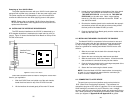
NOTE: If you do not have a terminal, you may force the unit to use the
DIP switches as the default configuration source by turning off the unit,
setting all the DIP switches to the ON position, then powering on the
unit. This will cause the unit to enter a special mode. Then turn off the
unit and change the switch settings to the desired settings. When you
turn the unit on again, the unit will be set up with the selected switch
settings.
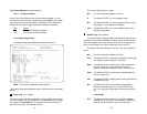
DS0 Channel Configuration Menu [ Bandwidth/# Channels =
2,048k/na]
(default)
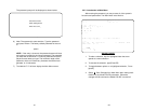
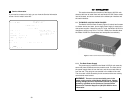
The Channel Configuration Menu has a sub-menu that looks
like this:
You may configure the Model 2701RC to operate with any combination
of active and inactive DS0 channels in this screen. When you execute
the Save Changes command, the selected settings will be saved to
permanent memory, and the system will be updated to operate with the
new channel settings.
NOTE: In Unframed format, the Bandwidth Selected will display
“2.048k,” and the Total Channels will display “na.” When using the
DIP switches to set the bandwidth, the starting channel is always
channel 1 or 0.
g
i
j
n
2701RC