


38
37
4.5 CONNECTING TO A DCE DEVICE
The rear interface cards on most interface modules are hard wired
as DCE . Therefore, you must use a
null modem
cable when con-
necting to a modem, multiplexer or other DCE device. This cable
should be of the shortest possible length--we recommend 6 feet or
less. When purchasing or constructing a null modem interface cable,
use the pin diagrams in Appendix C as a guide.
NOTE: Pin-out requirements for null modem applications
vary between equipment manufacturers. If you have any
questions about a specific installation, please contact Patton
Electronics Technical Support.
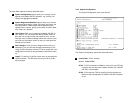
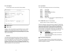
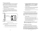
4.6 CONNECTING THE E1 INTERFACE
The Network Line Interface is an eight position keyed modular jack
configured as a RJ-48C. This interface will need to be configured to
match the line parameters (i.e. framing, line coding, etc.) supplied by
the central office.
NOTE: If the
NetLink-E1“ is being used for private short range modem appli-
cations, the twisted pair cable connected to its port will need to be
a cross-over cable. See Appendix D for Interface pin assignments.
4.7 CONNECTING DUAL COAX BNC (75 OHM)
In addition to the 120 Ohm twisted pair connection, the Model
2701RC, when used with the 1001RCM11575 rear card, is equipped
with dual female BNCs (TX and RX) for connection to a 75 ohm dual
coax G.703 network interface.
5.0 OPERATION
Once the NetLink-E1™ is installed and configured properly it is
ready to place into operation. This section describes the function of
the LED indicators, and the use of the loopback and pattern test
modes.
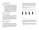
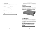
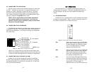
5.1 LED DESCRIPTIONS
The NetLink-E1™ is equipped with nine LED indicators that monitor
the status of communication. Figure 12 (below) shows the location of
the LEDs on the NetLink-E1™ Series front panel.
TXD When the unit sends a one, the TXD LED is
green. When it sends a zero, the TXD LED
is yellow. Moreover, the TXD LED is active
only in active DS0 channels. In inactive
channels, the TXD LED is off.
RXD When the unit receives a one, the RXD LED
is green. When it receives a zero, the RXD
LED is yellow. Moreover, the RXD LED is
active only in active DS0 channels. In inac-
tive channels, the RXD LED is off.
LOS The Loss of Sync LED lights when the unit
loses synchronization with the incoming sig-
nal. This may happen when there is a fram-
ing mismatch or a loss of signal. In
unframed mode, the LOS LED monitors the
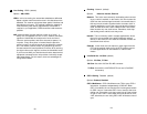
Figure 11. NetLink-E1“twisted pair line interface.
1 RX Data (TIP)
2 RX Data (RING)
3 (no connection)
4 TX Data (TIP)
5 TX Data (RING)
6 (no connection)
7 (no connection)
8 (no connection)
1
2
3
4
5
6
7
8
}
}
From Network
To Network
Figure 12. Model 2701RC front panel, showing LED indicators.
Model 2701RC