


13
14
The table below provides an overview of interface strap functions
for the rear interface cards. Following the table overview are detailed
descriptions of each strap’s function.
DTE Shield (DB-25 Pin 1) & FRGND (JB3)
In the connected position, this strap links DB-25 pin 1 & frame
ground. In the open position, pin 1 is disconnected from frame ground.
JB3
Position 1&2 = DTE Shield (Pin 1) and FRGND Connected
Position 2&3 = DTE Shield (Pin 1) and FRGND Not Connected
SGND & FRGND (JB4)
In the connected position, this strap links DB-25 pin 7 (Signal
Ground) and frame ground through a 100 ohm resistor. In the open
position, pin 7 is connected directly to frame ground.
JB4
Position 1&2 = SGND (Pin 7) and FRGND Connected through
a 100 ohm resistor
Position 2&3 = SGND (Pin 7) and FRGND Directly Connected
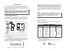
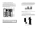
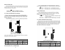
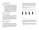
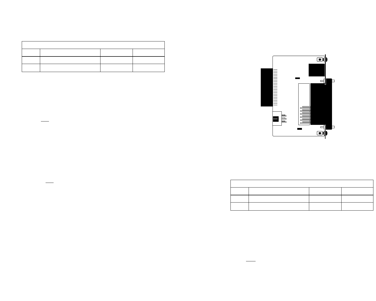
3.2.2 Model 1001RCM13448C Strap Settings
Figure 6 shows the strap location for the Model 1001RCM13448C
(M/34) rear card. This strap determines whether Signal Ground and
Frame Ground will be connected.
The table below provides an overview of interface strap functions
for the rear interface cards. Following the table overview are detailed
descriptions of each strap’s function.
DTE Shield (M/34 Pin A) & FRGND (JB3)
In the connected position, this strap links M/34 pin A & frame
ground. In the open position, pin A is disconnected from frame ground.
JB3
Position 1&2 = DTE Shield (Pin A) and FRGND Connected
Position 2&3 = DTE Shield (Pin A) and FRGND Not Connected
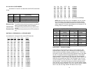
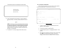
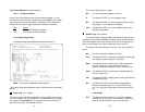
INTERFACE CARD STRAP SUMMARY TABLE #1
Strap Function Position 1&2 Position 2&3
JB3 DTE Shield (Pin1) & FRGND Connected* Open
JB4 FRGND & SGND Connected* Open
* Indicates default setting
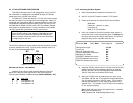
123
123
JB3
JB4
Figure 6. 1001RCM13448C strap locations
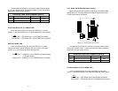
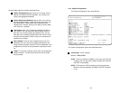
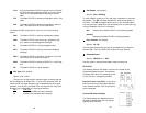
INTERFACE CARD STRAP SUMMARY TABLE #2
Strap Function Position 1&2 Position 2&3
JB3 DTE Shield (Pin A) & FRGND Connected* Open
JB4 FRGND & SGND (Pin B) Connected* Open
* Indicates default setting