


29
30
Tx1s If the remote Model 2701RC responds to the local Model
2701RCs terminate loopback request, the local unit then
sends an all ones pattern before returning to the Idle
state
TxP The Model 2701RC is sending a test pattern while in Test
Mode
IdlP The Model 2701RC is sending a test pattern in place of
data. The Model 2701RC is not in test mode.
The Model 2701RC receiving a RL can be in one of the following
states:
RxPr The Model 2701RC is receiving a preparatory pattern.
Sack The Model 2701RC, upon receiving a preparatory pat-
tern, sends an acknowledgement message.
RL The Model 2701RC is in remote loopback mode.
RxTr The Model 2701RC is receiving a terminate loopback
message.
WE1s The Model 2701RC is waiting for a sequence of all ones
and will time out if it does not receive it.
IdleP The Model 2701RC is sending a QRSS, 511 or 2047 pat-
tern.
Off The Model 2701RC is in local loopback.
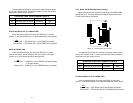
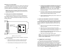
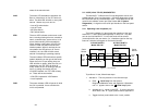
RDL Type: V.54
(default)
Options: V.54 or CSU
The user can set this switch to select the type of remote loop that
will be initiated by the Model 2701. If set to V.54, the Model 2701 will
initiate a V.54 loop when Remote Loop is selected by the front panel
switches. If set to CSU, the Model 2701 will initiate a CSU loop when
Remote Loop is selected by the front panel switches.
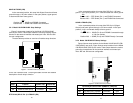
S2-3
RDL Type
Off Initiate a V.54 RDL loop when selected
On Initiate a CSU loopback when selected
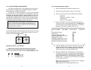
Test Pattern Idle
(default)
Options: Idle or Sending
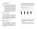
To send a pattern, press the ‘c’ key and press <spacebar> to send the
test pattern. The “OK” message indicates the received test pattern is
error-free. The “BE” message indicates errors in the received pattern.
You may also hear a beep (from your termainal) once a second as long
as the unit detects a bit error in the pattern.
Idle Indicates that Model 2701RC is not sending a pattern.
Sending
Indicates that Model 2701RC is sending a pattern.
Error Insertion Off
(default)
Options: On, Off
You may inject intentional errors into the test pattern by turning Error
Insertion ON. The Error (ERR) LED will blink once per second.
Selected Pattern
Options: QRSS, 511, or 2047
Use this option to select the test pattern used to test the link.
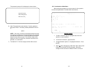
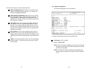
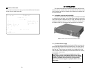
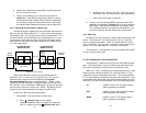
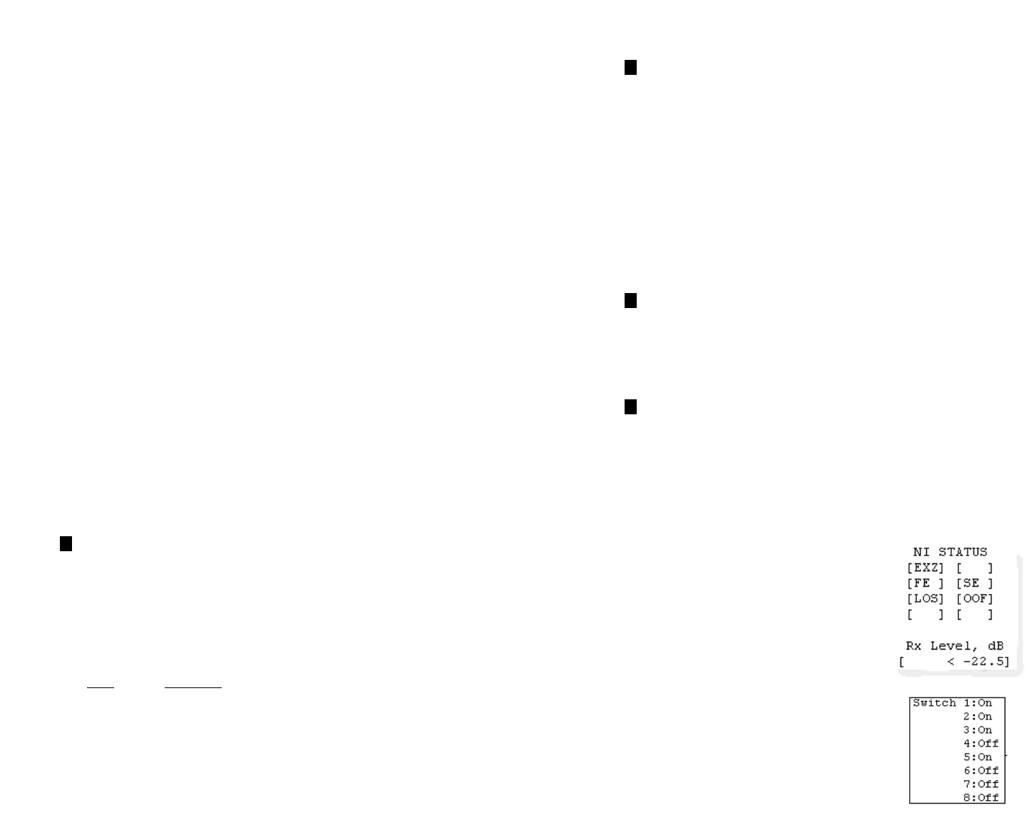
NI STATUS
The Network interface (NI) status is shown in the middle of the
Diagnostics/Statistics screen. The brackets
are empty when the link is operating normal-
ly. Only one error message is provided.
Receiver Carrier Loss [RCL] occurs when
255 consecutive zeros have been detected
at the network interface. RCL clears when a
pulse is detected.
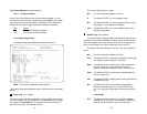
Current DIP Switch Settings
The Switch settings are displayed here to
facilitate troubleshooting your unit without
opening up the unit first.
e
c
f
d