


9
10
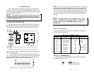
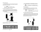
SWITCH S2-2: CRC-4 MULTIFRAME
In framed mode, S2-2 is used for CRC-4 MF. When CRC-4 is enabled,
the unit monitors the incoming data stream for CRC-4 errors. It trans-
mits CRC-4 error counts to the transmitting unit.. When using timeslot
zero (TS0), excessive errors may cause loss of frame or loss of sync.
If CRC-4 MF is used, both units must be set for set for CRC-4 MF.
Otherwise, the one using CRC-4 MF will detect loss of sync.
S2-2
Option
Off CRC-4 Disabled
On CRC-4 Enabled
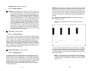
NOTE: When the data rate is set to 2.048Mb/s, then the unit is
forced into G.703 mode, and it transmits user data on all 32 time-
lots. There is no framing information; therefore, the CRC4 MF (S2-
2) switch is ignored. In all other rate settings, the unit employs
G.704 framing; TS0 is reserved for signaling.
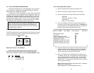
SWITCH S2-3: REMOTE DIGITAL LOOPBACK TYPE
The user can set this switch to select the type of remote loop that
will be initiated by the Model 2701. If set to V.54, the Model 2701 will
initiate a V.54 loop when Remote Loop is selected by the front panel
switches. If set to CSU, the Model 2701 will initiate a CSU loop when
Remote Loop is selected by the front panel switches.
S2-3
RDL Type
Off Initiate a V.54 RDL loop when selected
On Initiate a CSU loopback when selected
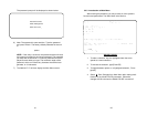
SWITCH S2-4: RDL RESPONSE
V.54 and CSU Loopbacks are special in-band loopback facility that
sends a pseudo-random pattern over the data stream. This is useful for
campus applications when you need to put a remote unit in loopback.
The unit responds to the V.54 loopback command, and the whole
process takes only a few seconds to complete. When V.54 Loopback
is disabled, the unit will not be able to send or respond to V.54 or CSU
loopback commands. The duration of the loopback is limited by the
loopback timeout setting.
S2-4
Option
Off RDL Response Disabled
On RDL Response Enabled
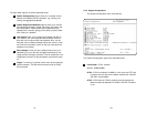
SWITCH S2-5 TEST MODE REQUEST FROM DTE
Use Switch S2-5 to allow Model 2701RC to enter loopback tests when
the DTE raises the appropriate loop request pin.
S1-8
Setting
Off Response to DTE Loopback Request Enabled
On Response to DTE Loopback Request Disabled
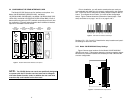
SWITCH S2-6 FRONT PANEL SWITCHES
As the Front Panel Switches may be inadvertently toggled, or in the
event that the end-user may not need to use the switches, the installer
may disable the front panel switches. Set Switch S2-6 to determine
whether the front-panel toggle switches are enabled or disabled.
S2-6
Option
On Front Panel Switches Enabled
Off Front Panel Switches Disabled
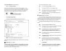
SWITCH S2-7 VT-100 OR NMS SELECTION
Switch S2-7 selects the configuration mode that the G.703 Access
Rack Card uses. When VT-100 is selected, configuration and status
can be setup through a VT-100 terminal using a 1001CC. When NMS
(network management station) is selected, configuration and status
can be setup and maintained through SNMP using a 1001MC. Please
refer to the 1001MC user manual when using this mode.
Note: Dip switch configuration can be used regardless of the setting of
this switch. The dip switches are enabled through the VT-100 screens,
NMS, or by performing a hardware reset.
S2-7
Management Selection
On NMS control
Off VT-100 control
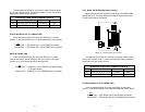
SWITCH S2-8 IMPEDANCE
Switch S2-8 is used to select the line build out for the Model 2701RC.
When using the 1001RCM11575 (dual BNC) rear card, set S2-8 to
OFF. When using a 120 Ohm cable with RJ-45 connectors, set S2-8 to
ON.
S2-8 Setting
75 Ohm OFF
120 Ohm ON