


11
12
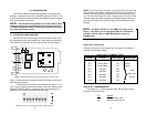
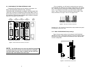
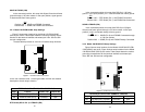
3.2 CONFIGURING THE REAR INTERFACE CARD
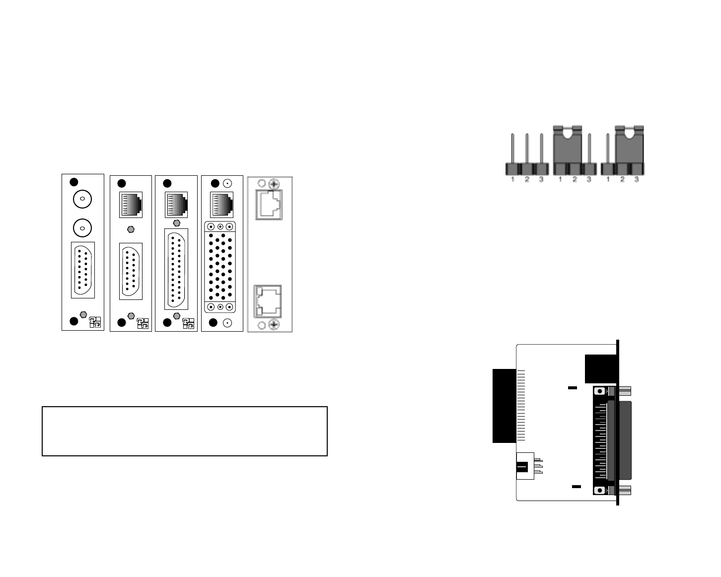
The Model 2701RC Series has five interface card options: the
Model 1001RCM12548C (DB-25/RJ-48C), the Model
1001RCM13448C (M/34/RJ-48C), the Model 1001RCM11548C (DB-
15/RJ-48C), the Model 1001RCM11575 (DB-15/Dual BNC). Each of
these options supports one DTE interface connection and one 4-wire
line connection. Figure 3 below illustrates the five different interface
options for the Model 2701RC Series.
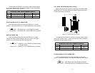
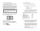
Prior to installation, you will need to examine the rear card you
have selected and make sure it is properly configured for your applica-
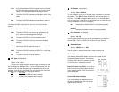
tion. Each rear card is configured by setting straps located on the PC
board. To configure the rear cards, you must set the configuration
straps. Figure 4 below shows the orientation of these straps. Each
strap can either be on pegs 1 and 2, or on pegs 2 and 3.
Sections 3.2.1, 3.2.2, and 3.2.3 describe the strap locations and possi-
ble settings for each rear card.
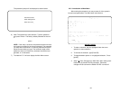
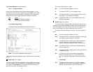
3.2.1 Model 1001RCM12548C Strap Settings
Figure 5 shows strap locations for the Model 1001RCM12548C
(DB-25) rear cards. These straps determine various grounding charac-
teristics for the terminal interface and twisted pair lines. JB3 and JB4
are user configurable.
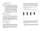
Figure 3. Model 2701RC Series interface card options
DB-15 F
M/34 F
DB-25 F
Model
1001RCM12548C
Model
1001RCM11548C
Model
1001RCM13448C
RJ-48C
RJ-48C
RJ-48C
NOTE: The 2701RC Series rear cards are specifically designed
to operate with the E1 function card and must not be swapped
with other Patton function cards. In addition the rear card must
match the flip card installed on the front card.
123
JB3
JB4
123
Figure 5. 1001RCM125XX strap locations
Figure 4. Orientation of Interface Card Straps
Model
1001RCM11575
Dual BNC
DB-15 F
Model
IM2RC/IA
RJ-48C