


7
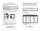
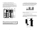
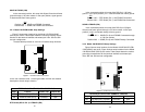
S1-2 and S1-3 CLOCK MODES
Set switch S1-2 and S1-3 to determine the 2701RC’s transmitter
timing.
Network Clock Transmitter timing is derived using the received line
signal (received recovered) from the network.
Internal Clock Transmitter timing is derived from an internal clock
source.
External Clock Transmitter timing is derived from DTE terminal tim
ing.
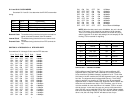
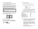
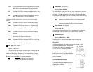
SWITCH S1-4 THROUGH S1-8: DTE DATA RATE
Use switches S1-4 through S1-8 to set the DTE data rate.
S1-4
S1-5 S1-6 S1-7 S1-8 Speed
ON OFF OFF OFF OFF 64kbps
OFF ON OFF OFF OFF 128kbps
ON ON OFF OFF OFF 192kbps
OFF OFF ON OFF OFF 256kbps
ON OFF ON OFF OFF 320kbps
OFF ON ON OFF OFF 384kbps
ON ON ON OFF OFF 448kbps
OFF OFF OFF ON OFF 512kbps
ON OFF OFF ON OFF 576kbps
OFF ON OFF ON OFF 640kbps
ON ON OFF ON OFF 704kbps
OFF OFF ON ON OFF 768kbps
ON OFF ON ON OFF 832kbps
OFF ON ON ON OFF 896kbps
ON ON ON ON OFF 960kbps
OFF OFF OFF OFF ON 1024kbps
ON OFF OFF OFF ON 1088kbps
OFF ON OFF OFF ON 1152kbps
ON ON OFF OFF ON 1216kbps
OFF OFF ON OFF ON 1280kbps
ON OFF ON OFF ON 1344kbps
OFF ON ON OFF ON 1408kbps
ON ON ON OFF ON 1472kbps
OFF OFF OFF ON ON 1536kbps
ON OFF OFF ON ON 1600kbps
OFF ON OFF ON ON 1664kbps
ON ON OFF ON ON 1728kbps
OFF OFF ON ON ON 1792kbps
ON OFF ON ON ON 1856kbps
OFF ON ON ON ON 1920kbps
ON ON ON ON ON 1984kbps
OFF OFF OFF OFF OFF Clear Channel 2048kbps
NOTE: When the data rate is set to 2.048Mb/s, the unit is forced
into G.703 mode, and it transmits user data on all 32 time-lots.
There is no framing information; therefore, the CRC4 MF (S2-2)
switch is ignored. In all other rate settings, the unit employs G.704
framing; TS0 is reserved for signaling.
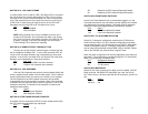
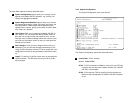
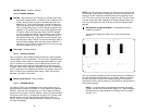
SWITCH S2-1: CAS MULTIFRAME
CAS multiframe uses Timeslot 16 (TS16) to send multiframe (MF)
alignment data. In CAS MF, a MF is defined as 16 frames, where a
frame consists of 32 64kb/s timeslots, numbered 0 to 31. TS16 of the
first frame in the MF contains the CAS MF alignment word in the upper
four bits. The alignment word is always 0000 (binary). The 2701RC
does not perform any signaling in TS16 other than to insert the MF
alignment word, in order to maintain MF alignment. When CAS MF dis-
abled, the unit transmits user data in TS16; therefore, up to 31 chan-
nels are available for user data. When it is enabled, TS16 is not avail-
able to the user. In this case, the user can use up to 30 channels for
data. CAS MF can be used with CRC-4 MF or by itself. When enabled,
both units must employ CAS MF; if one unit is set for CAS MF, and the
other is not, the one using CAS MF will detect a loss of sync.
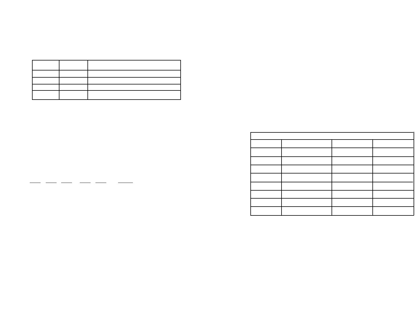
S1-2 S1-3 Clock Mode
On On Network (Recieved Recovered)
Off On Internal
On Off External
Off Off Network (Recieved Recovered)
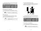
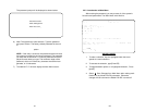
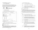
SWITCH SET 2 SUMMARY TABLE
Position Function Factory Default Selected Option
S2-1 CAS MF OFF Disabled
S2-2 CRC-4 multiframe OFF Disabled
S2-3 RDL Type OFF V.54
S2-4 RDL Response ON
Enabled
S2-5 TM from DTE ON Enabled
S2-6 Front Panel Switch ON Enabled
S2-7 NMS/VT-100 Switch OFF VT-100
S2-8 Line build out ON 120 Ohms
8