


41
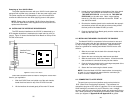
2. Verify that the data terminal equipment is operating properly
and can be used for a test.
3. Perform a V.52 BER (bit error rate) test as described in
Section 5.3. If the BER test equipment indicates no faults,
but the data terminal indicates a fault, follow the manufactur-
er s checkout procedures for the data terminal. Also, check
the interface cable between the terminal and the NetLink-E1.
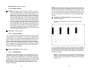
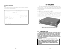
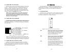
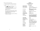
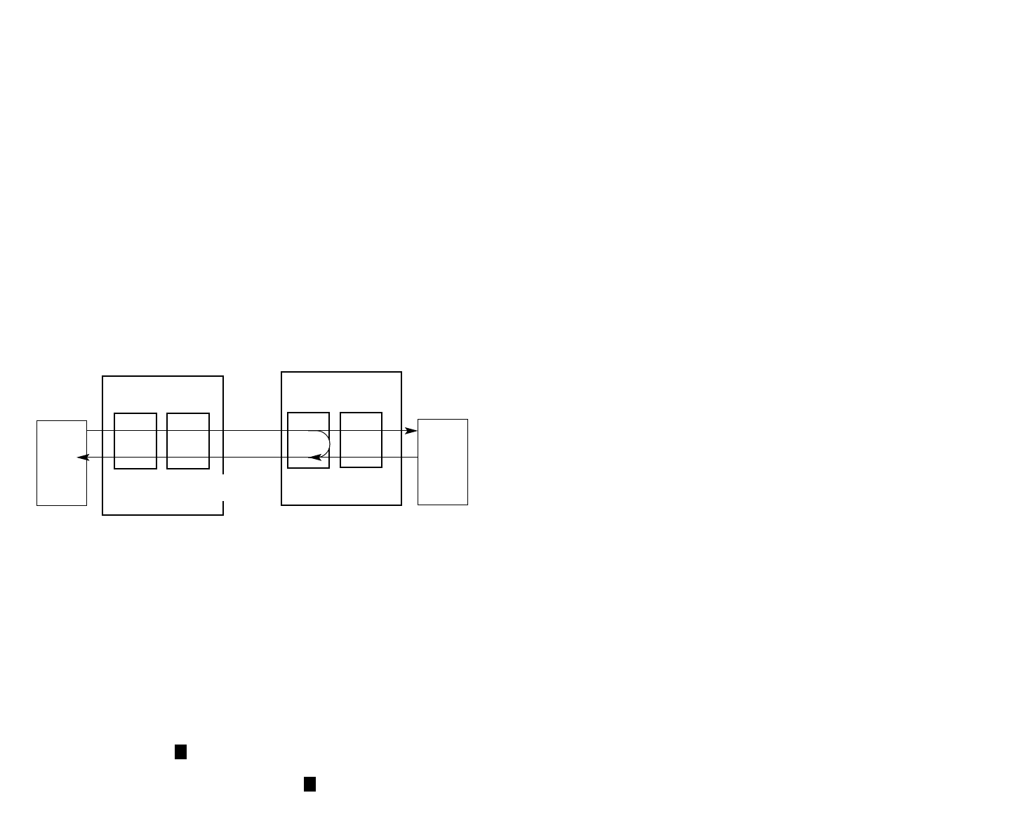
5.2.2 Operating Remote Digital Loopback (RL)
The Remote Digital Loopback (RL) test checks the performance of
both the local and remote NetLink-E1™, as well as the communication
link between them. Any characters sent to the remote NetLink-E1™ in
this test mode will be returned back to the originating device (i.e, char-
acters typed on the keyboard of the local terminal will appear on the
local terminal screen after having been passed to the remote NetLink-
E1™ and looped back).
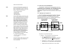
There are two Remote Loops that can be initiated from the
NetLink-E1 unit: (1) V.54 Loop, and; (2)CSU Loop. The user can
select the type of loop that can be initiated from the System
Diagnostics/Statistics screen or with Switch S2-1. Select c RDL
Type and press the <spacebar> to toggle between the CSU loop and
the V.54 loop. When a loopback is initiated this is the type of loop that
the unit uses to loop up the remote unit. NOTE: The NetLink-E1 will
respond to both loops regardless of the state of the RDL Type.
To perform an RDL test, follow these steps:
1. Activate RDL. This may be done in three ways:
a. Enter Remote Loop from the System
Diagnostics/Statistics menu and toggle the <Spacebar>
until RL appears next to the Remote Loop option.;
b. Activate the RL signal on the DTE. If you are not sure
which lead is the RL signal, please refer to Appendix D.
c. Set the front panel switch to Remote .
2. Perform a bit error rate test (BERT) using the internal V.52
generator (as described in Section 5.3), or using a separate
BER Tester. If the BER test indicates a fault, and the Local
Line Loopback test was successful for both NetLink“s, you
may have a problem with the twisted pair line connection.
5.2.3 CSU Loop
The NetLink-E1“ also responds to central office initiated loop com-
mands. The NetLink-E1“ will implement the loop up command
when it recognizes the pattern 10000 in the data stream for a mini-
mum of 5 seconds. The loop down command is implemented by the
pattern 100 in the data stream for a minimum of 5 seconds.
The NetLink-E1™ will respond to Universal Loopback De-activate
to clear all central office loops.
5.3 BIT ERROR RATE (V.52) DIAGNOSTICS
The NetLink-E1™ offers three V.52 Bit Error Rate (BER) test pat-
terns. These test patterns may be invoked along with the LAL and
RDL tests to evaluate the unit(s) and the communication links.
When a 511, 2047, or QRSS test is invoked, the NetLink-E1™ gen-
erates a pseudo-random bit pattern of 511 bits, 2047 bits or 2
20
bits,
respectively, using a mathematical polynomial. The receiving NetLink-
E1™ then decodes the received bits using the same polynomial. If the
received bits match the agreed upon pseudo-random pattern, then the
NetLink-E1™(s) and the communication link(s) are functioning properly.
511 Initiates a built-in 511 bit pseudo-random
pattern generator and detector.
2047 Initiates a built-in 2047 bit pseudo-random
pattern generator and detector.
QRSS Initiates a built-in 2
20
bit pseudo-random
pattern generator and detector.
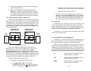
b
b
Figure 8. Remote Loopback
Serial
Device
Ethernet
Device
Model 2701RC
Receive
Recover
Clocking
Internal
Clocking
Cable Span
G.703/G.704 NTU
Model 2701 RC
G.703/G.704 NTU
Model 2701 RC
Clock/
Data
Clock/
Data
Clock/
Data
Data
Data
Model 2701RC
RDL Initiated
42