


Hardware overview 21
Model 3196RC T-DAC User Manual 1 • Introduction
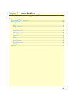
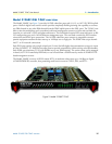
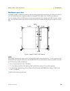
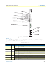
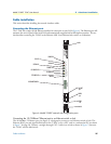
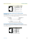
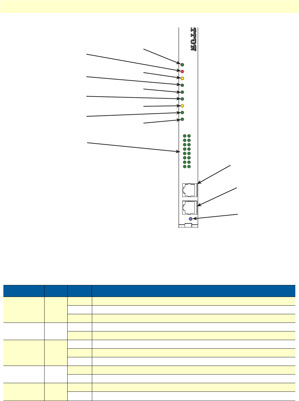
Figure 4. Model 3196RC front panel LEDs
LED display
Front panel LEDs (figure 3) display the status of the WAN ports, the iDSL ports, the Ethernet LAN port,
power, and the alarms. The LEDs are described in table 3.
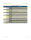
Table 3. LED definitions
LED Color Status Meaning
POWER Green On solid Power is being applied. No action recommended.
Flashing The 3196RC has detected a power failure on a power bus.
Off No input power is being applied.
CPU FAIL Red On solid CPU is unable to load the software from FLASH to RAM for operation.
Off The CPU is operating normally.
ALARM Yellow On solid A minor alarm condition has been detected.
Flashing A major alarm condition has been detected.
Off The Model 3196RC is operating normally.
SYSTEM Green Flashing The Model 3196RC is operating normally.
Off The Model 3196RC is not functioning properly.
ETHERNET Green On solid Link status is nominal for the Ethernet port. No action recommended.
Off
A valid link has not been detected.
DSL
on
centrator
R
C T-DAC
WAN
POWER
ETHERNET
CLK ERROR
SYSTEM
TEST MODE
CPU FAIL
ALARM
CLK SOURCE
DSL CONNECTION
2
3
4
5
6
7
8
10
11
12
13
14
15
16
1
9
CONFIG
10/100 ENET
READY
10/100 ENET
port
CONFIG
port
READY
LED
DSL CONNECTION LEDs
TEST MODE LED
CLK SOURCE LED
SYSTEM LED
CPU LED
WAN LED
CLK ERROR LED
ETHERNET LED
ALARM LED
POWER LED