


Pelco Manual C523M-H (6/05) 11
4 CONNECT CONTROL LINES
1. Connect camera control lines to receivers. If your video sources are all controlled by
Coaxitron, skip this section and go to step 5 . If any of your video sources are using D
or P protocol via RS-422 communications circuits, they will connect at COM 1 on the
back of the SCU, as outlined below.
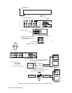
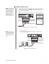
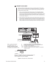
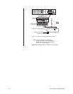
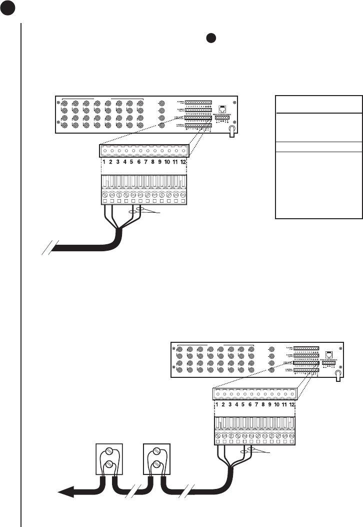
2. Refer to Figure 10. Connect control lines to COM 1 at the connector on the back of the
SCU.
NOTE:
If D or P protocol
receivers are used, they must
all be the same protocol. D
and P protocol receivers
cannot be mixed on the
SCU’s communication port.
Coaxitron control may be
used for some of your
sources when either D or P
protocol receivers are used.
Figure 10. COM 1 Connections on the SCU
TO RECEIVERS
12-PIN PLUG-IN
CONNECTOR
COM 1 (1-6)
COM 2 (7-12)
NOTE: TO PROPERLY
SHIELD DATA CABLE
CONNECT GROUND
ON ONE END ONLY
CONNECT PINS 5 & 6 ONLY IF
USING BI-DIRECTIONAL CONTROL
VIDEO INPUTS
1 3 5 7 9 1 13 15
2 4 6 8 10 12 14 16
VIDEO OUTPUTS
1
2
3
4
LOCAL
KEYBOARD
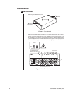
COM 1 (1-6)
RS-422
PIN ASSIGNMENTS
PIN FUNCTION
1T+
2T–
3 (OPTIONAL) GND
4 NC
5R–
6R+
00052
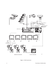
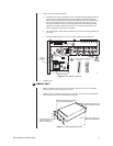
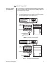
3. Connect wiring to all receivers.
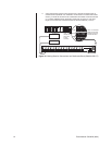
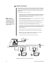
a. Daisy-chaining (going from one receiver to another) is recommended (refer to
Figure 11) but not always possible.
NOTE:
Unless you have
receivers that are equipped
for bi-directional control, you
will only need to run two
wires (TX+ and TX-) to each
receiver.
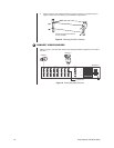
Figure 11. Daisy-Chaining Receivers
VIDEO INPUTS
1 3 5 7 9 1 13 15
2 4 6 8 10 12 14 16
VIDEO OUTPUTS
1
2
3
4
LOCAL
KEYBOARD
00050
TO SCU
12-PIN PLUG-IN
CONNECTOR
COM 1 (1-6)
COM 2 (7-12)
NOTE: TO PROPERL
Y
SHIELD DATA CABLE
CONNECT GROUND
ON ONE END ONLY
CONNECT PINS 5 & 6 ONLY
FOR BI-DIRECTIONAL CONTROL
DAISY-CHAINING
RECEIVER 2 RECEIVER 1
RX- RX-
RX+ RX+
TO ADDITIONAL
RECEIVERS