


14 Pelco Manual C523M-H (6/05)
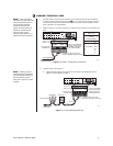
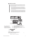
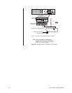
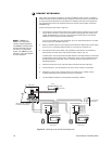
6 CONNECT ALARMS
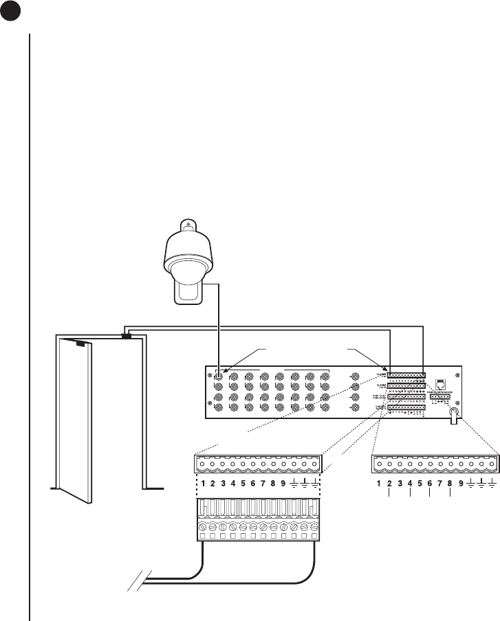
1. Refer to Figure 14. Alarm inputs 1-16 correspond to video inputs 1-16. If an open door
sensor is connected to alarm input 1, when the sensor is activated the video image
from camera 1 will be displayed on one of the four monitors and the camera will move
to a preset (determined by programming). Alarm sensors can be either N.O. or N.C.
contacts. Connect wires from the sensors to the respective alarm input points on the
connectors at the back of the SCU. Each sensor requires one wire to the alarm input
terminal and a return wire to one of the ground terminals on the connector.
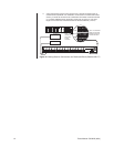
2. Alarm inputs 17 and 18 correspond to group sequences 1 and 2. During a group
sequence four video inputs are sequentially shown on a monitor. Each of the four
monitors can be programmed to show the images from four different video sources.
An alarm sensed at input 17 or 18 causes the respective group sequence to operate.
Connect sensors for these two alarm inputs as described in step 1 above.
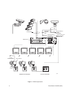
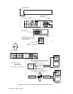
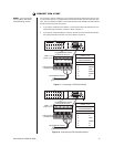
Figure 14. Connecting Alarms
VIDEO INPUTS
1 3 5 7 9 1 13 15
2 4 6 8 10 12 14 16
VIDEO OUTPUTS
1
2
3
4
LOCAL
KEYBOARD
VIDEO INPUT CORRESPONDS
TO ALARM INPUT
CAMERA 1
(10)
(11)
(12)
(13)
(14)
(15)
(16)
(17)
(18)
00047
TO ALARM SOURCE
12-PIN PLUG-IN
CONNECTOR
ALARMS
(1-9)
ALARMS
(10-18)
12-PIN TERMINAL STRIP
ON REAR OF SCU