


8 Pelco Manual C523M-H (6/05)
INSTALLATION
1 SET OPTIONS
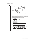
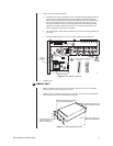
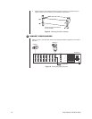
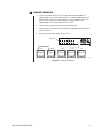
1. Refer to Figure 4. Remove the cover.
Figure 4. Cover Removal
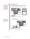
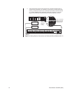
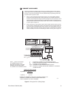
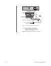
2. Refer to Figure 5. Set jumpers according to your system requirements. JP1-JP16 are
used to terminate the video input with a 75-ohm resistor or to unterminate the video
(looping). The factory default has the jumper installed in the terminating position. If you
are connecting only a camera to an input, leave the jumper in the terminating position.
If you are looping the video to another device, move the jumper to the looped position,
and terminate at the equipment connected to the looping output.
REMOVE 6
SCREWS
REMOVE 6
SCREWS
LIFT COVER
OFF
A
B
C
00055
ON
1234
ON
1234
ON
1234
75-OHM TERMINATION
JUMPERS (ONE PER INPUT)
ON
1234
BACK OF SCU
JP1
JP16
NOTE: JUMPER JP1 CORRESPONDS TO VIDEO INPUT 1,
JP2 TO VIDEO INPUT 2, ETC.
75-OHM TERMINATION
JUMPER
TERMINATED LOOPED
KEY
Figure 5. Video Termination Jumpers