


18 Pelco Manual C523M-H (6/05)
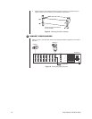
9 CONNECT KEYBOARDS
Pelco offers three keyboard models for use with the CM6700 matrix switcher. Complete in-
stallation instructions are provided with each keyboard. The most common connections are
for local and remote keyboards. The procedures for installing local and remote keyboards
are repeated here. Refer to the keyboard manual for the less common ASCII connection
(KBD200A only).
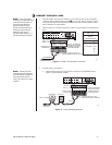
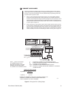
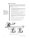
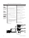
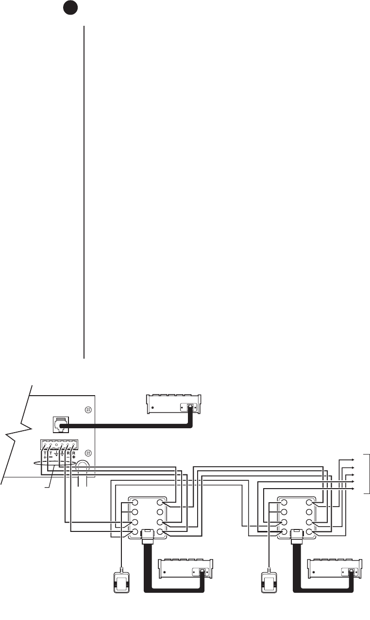
Do the following to install. Refer to Figure 19.
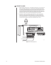
1. Local keyboard. Using the data cable that is supplied with the keyboard, plug one end
into the RJ-45 connector on the rear of the keyboard and plug the other end into the
LOCAL KEYBOARD port on the SCU. Set the keyboard DIP switch for the desired
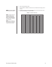
address for the local keyboard (refer to Table A).
If you are not installing any other keyboards, go to the
Programming
section. To install
remote keyboards, complete steps 2-10.
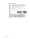
2. Select a suitable location for each keyboard and wall block. Wall blocks must be within
6 feet (1.8 m) of a suitable electrical outlet. Do not mount the wall block yet.
3. Run wall block interconnect cable (user-supplied) from the SCU to the closest key-
board location, and then to the next nearest location, and the next, etc.
Communication to the keyboards is RS-485. Maximum total cable distance for RS-485
communication over 24-gauge wire is 4,000 feet (1,219 m). Pelco recommends using
shielded twisted pairs cable that meets or exceeds the basic requirements for EIA
RS-485 applications.
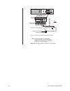
4. Remove the wall block cover and make cable connections at each wall block.
5. At each wall block, wire the transformer to pins 3 and 4. Polarity is unimportant.
6. Replace the cover on the wall block. Secure the wall block to a suitable surface.
A double-sided sticky pad is provided to mount the wall block.
7. Set the address switches for each keyboard according to Table A.
NOTE:
A KBDKIT or
KBDKIT-X is required to
connect remote keyboards.
The KBDKIT consists of two
RJ-45 wall blocks and one
120 VAC to 12 VAC trans-
former. The KBDKIT-X is for
230 VAC. Use one wall block
for each keyboard.
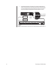
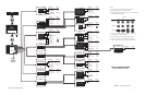
Figure 19. Installing Local and Remote Keyboards
25-FOOT KEYBOARD DATA
KBD
LOCAL
KEYBOARD
LOCAL
KEYBOARD
REMOTE KEYBOARD(S)
USER-SUPPLIED CABLE
TO REMOTE KEYBOARDS
CM6700 SCU
25-FOOT KEYBOARD
DATA CABLE
2
3
4
5
6
7
18
25-FOOT KEYBOARD
DATA CABLE
2
3
4
5
6
7
18
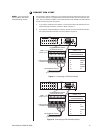
RX+
RX-
TX+
TX-
GND
TO ADDITIONAL
KEYBOARDS
REMOTE KEYBOARD
12 VAC 12 VAC
WALL BLOCK TERMINALS WALL BLOCK TERMINALS
REMOTE KEYBOARD