


Pelco Manual C523M-H (6/05) 17
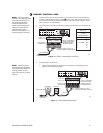
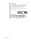
8 CONNECT COM 2 PORT
You will need to use the COM 2 port if your system includes an ASCII control device, such
as a personal computer or a keyboard that is connected via dial-up lines or fiber optic net-
work. The port interface at COM 2 can be either RS-232 or RS-422/485. The DIP switches
should have been set (refer to Figure 6).
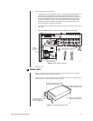
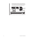
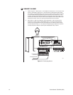
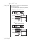
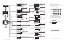
a. If you require an RS-232 port interface, connect wires from the RS-232 device to the
COM 2 terminals at the back of the SCU. Refer to Figure 17.
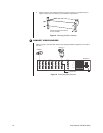
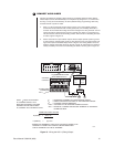
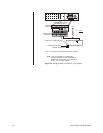
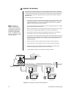
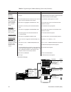
b. If you require an RS-422/485 port interface, connect wires from the RS-422 device to
the COM 2 terminals at the back of the SCU. Refer to Figure 18.
Figure 17. Connecting an RS-232 Interface
VIDEO INPUTS
1 3 5 7 9 1 13 15
2 4 6 8 10 12 14 16
VIDEO OUTPUTS
1
2
3
4
LOCAL
KEYBOARD
10
12-PIN PLUG-IN
CONNECTOR
COM 1 (1-6)
COM 2 (7-12)
12-PIN TERMINAL STRIP
ON REAR OF SCU
TO EXTERNAL DEVICE
TX+ GND RX+
COM 2 (7-12)
RS-232
PIN ASSIGNMENTS
PIN FUNCTION
7T+
8SPARE
9 GND
10 SPARE
11 SPARE
12 R+
VIDEO INPUTS
1 3 5 7 9 1 13 15
2 4 6 8 10 12 14 16
VIDEO OUTPUTS
1
2
3
4
LOCAL
KEYBOARD
10
12-PIN PLUG-IN
CONNECTOR
COM 1 (1-6)
COM 2 (7-12)
12-PIN TERMINAL STRIP
ON REAR OF SCU
TO EXTERNAL DEVICE
RX+
RX-
GND
TX-
TX+
COM 2 (7-12)
RS-422/485
PIN ASSIGNMENTS
PIN FUNCTION
7T+
8T-
9 GND
10 SPARE
11 R-
12 R+
Figure 18. Connecting an RS-422/485 Interface
NOTE:
If you are using a
PC at COM 2, refer to the
Troubleshooting
section.