


Pelco Manual C523M-H (6/05) 9
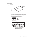
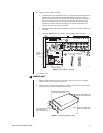
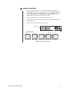
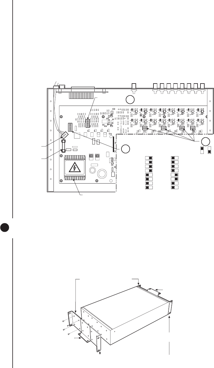
3. Refer to Figure 6. Set DIP switches.
a. Communication port 2 is available for a PC or remote keyboard operating in ASCII
mode. (Refer to
ASCII Operating Commands
.) Most PC applications require
RS-232. A remote keyboard can require either RS-232 or RS-422, depending on
the communications facility. To find out the required interface, check your PC
serial port information or refer to your keyboard manual. Set DIP switch SW5
(COM 2) for RS-232 or RS-422, according to your system requirements. The
SCU is configured at the factory for RS-422.
b. DIP switches SW1, SW2, SW3 and SW4 are to remain in the factory default posi-
tion (OFF).
c. DIP switch SW6 (COM1) is to remain in factory default position (RS-422).
Figure 6. DIP Switch Locations
4. Replace cover.
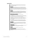
2 MOUNT UNIT
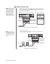
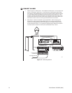
1. Select a suitable location for the SCU. It must be within 6 feet (1.8 m) of a suitable
electrical outlet. Do not connect the power yet.
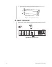
2. Refer to Figure 7. Position mounting ears on the sides of the SCU for the appropriate
mounting. If the ears are not required, leave them off.
ON
1234
ON
1234
ON
1234
ON
12345678
ON
12345678
POWER
TERMINAL
BLOCK
FUSE
TRANSFORMER
ON
12345678
ON
SW5 & 6 DIP SWITCH SETTINGS
RS-422/485 RS-232
12345678
OFF
KEY
ON
SW6 DEFAULTS
TO RS-422
3c
3a
3b
ON
1234
HIGH VOLTAGE
00054
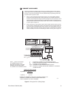
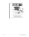
Figure 7. Installing Mounting Ears
POSITION BRACKETS FOR
FLUSH MOUNTING
(WALL OR TABLE TOP)
POSITION BRACKETS FOR
UNDER-TABLE MOUNTING
POSITION BRACKETS FOR
RACK MOUNTING (REAR)
NOTE: EACH SCU COMES WITH
2 MOUNTING BRACKETS