


Philips Semiconductors Product specification
PDIUSBH12USB 2-port hub
1999 Jul 22
11
COMMAND DESCRIPTIONS
Command Procedure
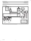
There are four basic types of commands: Initialization, Data, Hub
Specific, and General commands. Respectively, these are used to
initialize the hub and embedded function; for data flow between the
hub, embedded function, and the host; some hub specific
commands for controlling individual downstream ports; and some
general commands.
Initialization Commands
Initialization commands are used during the enumeration process of
the USB network. These commands are used to enable the hub and
embedded function endpoints. They are also used to set the USB
assigned address.
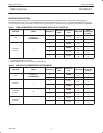
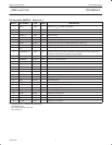
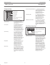
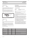
Set Address / Enable
Command : D0h (Hub), D1h, D2h, D3h,
(Embedded Functions)
Data : Write 1 byte
This command is used to set the USB assigned address and enable
the hub or embedded functions respectively. The hub powers up
enabled and needs not be enabled by the firmware at power up
initialization.
765432
0
1
0
0
POWER ON VALUE
ADDRESS
ENABLE
SV00825
000000
Address The value written becomes the address.
Enable A ‘1’ enables this function.
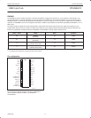
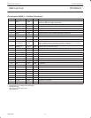
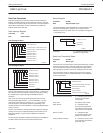
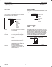
Set Endpoint Enable
Command : D8h
Data : Write 1 byte
The hub’s interrupt endpoint and the embedded functions generic
endpoints can only be enabled when the corresponding hub/function
is enabled via the Set Address/Enable command.
SV00841
765432
0
1
0
0
POWER ON VALUE
EMBEDDED FUNCTION 1 GENERIC ENDPOINTS
00XXXX
RESERVED
EMBEDDED FUNCTION 7 GENERIC ENDPOINTS
HUB’S INTERRUPT ENDPOINT
EMBEDDED FUNCTION 6 GENERIC ENDPOINTS
Hub’s Interrupt Endpoint A value of ‘1’ indicates
the hub’s interrupt
endpoint is enabled.
Embedded Function 1 Generic Endpoint A value of ‘1’ indicates
the embedded function
1 generic endpoints are
enabled.
Embedded Function 6 Generic Endpoint A value of ‘1’ indicates
the embedded function
6 generic endpoints are
enabled.
Embedded Function 7 Generic Endpoint A value of ‘1’ indicates
the embedded function
7 generic endpoints are
enabled.
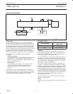
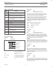
Set Mode
Command : F3h
Data : Write 2 bytes
The Set Mode command is followed by two data writes. The first
byte contains the configuration byte values. The second byte is the
clock division factor byte.