


Philips Semiconductors Product specification
PDIUSBH12USB 2-port hub
1999 Jul 22
12
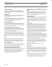
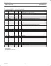
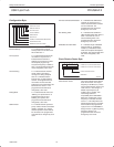
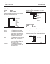
Configuration Byte
SV00842
POWER ON VALUE
REMOTE WAKEUP
NO LAZYCLOCK
CLOCK RUNNING
DEBUG MODE
SoftConnect
CONNECT DOWNSTREAM RESISTORS
NON-BLINKING LEDs
765432
0
1
1
0
110010
EMBEDDED FUNCTION MODE
Remote Wakeup A ‘1’ indicates that a remote
wakeup feature is ON. Bus reset
will set this bit to ‘1’.
No LazyClock A ‘1’ indicates that CLKOUT will
not switch to LazyClock. A ‘0’
indicates that the CLKOUT
switches to LazyClock 1ms after
the Suspend pin goes high.
LazyClock frequency is 30KHz (±
40%). The programmed value will
not be changed by a bus reset.
Clock Running A ‘1’ indicates that the internal
clocks and PLL are always
running even during Suspend
state. A ‘0’ indicates that the
internal clock, crystal oscillator
and PLL are stopped whenever
not needed. To meet the strict
Suspend current requirement, this
bit needs to be set to ‘0’. The
programmed value will not be
changed by a bus reset.
Debug Mode A ‘1’ indicates that all errors and
“NAKing” are reported and a ‘0’
indicates that only OK and
babbling are reported. The
programmed value will not be
changed by a bus reset.
SoftConnect A ‘1’ indicates that the upstream
pull-up resistor will be connected if
VBUS is available. A ‘0’ means
that the upstream resistor will not
be connected. The programmed
value will not be changed by a bus
reset.
Connect Downstream Resistors A ‘1’ indicates that downstream
resistors are connected. A ‘0’
means that downstream resistors
are not connected. The
programmed value will not be
changed by a bus reset.
Non-blinking LEDs A ‘1’ indicates that GoodLink
LEDs will NOT blink when there is
traffic. Leave this bit at ‘0’ to
achieve blinking LEDs. The
programmed value will not be
changed by a bus reset.
Embedded Function Mode A ‘1’ indicates single embedded
function mode. A ‘0’ indicates
multiple (3) embedded function
mode. See
endpoint descriptions
for details. The programmed value
will not be changed by a bus
reset.
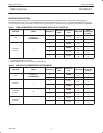
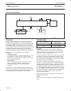
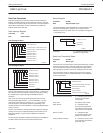
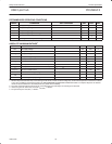
Clock Division Factor Byte
SV00843
765432
1
1
1
0
POWER ON VALUE FOR 48MHz INPUT
0000XX
111011XX
POWER ON VALUE FOR 12MHz INPUT
CLOCK DIVISION FACTOR
RESERVED
Clock Division Factor The value indicates clock division
factor for CLKOUT. The output
frequency is 48 MHz/(N+1) where
N is the Clock Division Factor. The
reset value is 3. This will give a
default output frequency at
CLKOUT pin of 12 MHz, thus
maintaining backward
compatibility to the PDIUSBH11.
When the 12 MHz input crystal
frequency is selected, the reset
value is 11. This will produce the
lowest output frequency of 4 MHz
which can then be programmed
up by the user. The PDIUSBH12
design ensures no glitching during
frequency change. The
programmed value will not be
changed by a bus reset.