


Philips Semiconductors Product specification
PDIUSBH12USB 2-port hub
1999 Jul 22
4
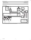
Analog Transceivers
These transceivers interface directly to the USB cables through
some termination resistors. They are capable of transmitting and
receiving serial data at both “full speed” (12 Mbit/s) and “low speed”
(1.5 Mbit/s) data rates.
Hub Repeater
The hub repeater is responsible for managing connectivity on a per
packet basis. It implements packet signaling connectivity and
resume connectivity.
Low speed devices can be connected to downstream ports since the
repeater will not propagate upstream packets to downstream ports,
to which low speed devices are connected, unless they are
preceded by a PREAMBLE PID.
End of Frame Timers
This block contains the specified EOF1 and EOF2 timers which are
used to detect loss-of-activity and babble error conditions in the hub
repeater. The timers also maintain the low-speed keep-alive strobe
which is sent at the beginning of a frame.
General and Individual Port Controller
The general and individual port controllers together provide status
and control of individual downstream ports. Via the I
2
C-interface a
microcontroller can access the downstream ports and request or
change the status of each individual port.
Any change in the status or settings of the individual port will result
in an interrupt request. Via an interrupt register, the servicing
microcontroller can look up the downstream port which generated
the interrupt and request its new status. Any port status change can
then be reported to the host via the hub status change (interrupt)
endpoint.
PLL
A 12 MHz to 48 MHz clock multiplier PLL (Phase-Locked Loop) is
integrated on-chip. This allows for the use of low-cost 12 MHz
crystal. EMI is also minimized due to lower frequency crystal. No
external components are needed for the operation of the PLL.
Bit Clock Recovery
The bit clock recovery circuit recovers the clock from the incoming
USB data stream using 4X over-sampling principle. It is able to track
jitter and frequency drift specified by the USB specification.
Philips Serial Interface Engine (PSIE)
The Philips SIE implements the full USB protocol layer. It is
completely hardwired for speed and needs no firmware intervention.
The functions of this block include: synchronization pattern
recognition, parallel/serial conversion, bit stuffing/de-stuffing, CRC
checking/generation, PID verification/generation, address
recognition, handshake evaluation/generation.
Memory Management Unit (MMU) and Integrated
RAM
The MMU and the integrated RAM is used to handle the large
difference in data rate between USB, running in bursts of 12 Mbit/s
and the I
2
C interface to the microcontroller, running at up to
1 Mbit/s. This allows the microcontroller to read and write USB
packets at its own speed through I
2
C.
I
2
C Slave Interface
This block implements the necessary I
2
C interface protocol. A slave
I
2
C allows for simple micro-coding. An interrupt is used to alert the
microcontroller whenever the PDIUSBH12 needs attention. As a
slave I
2
C device, the PDIUSBH12 I
2
C clock: SCL is an input and is
controlled by the microcontroller. The I
2
C interface can run up to 1
Mbit/s.
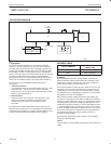
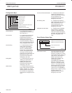
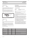
SoftConnect
The connection to the USB is accomplished by bringing D+ (for
high-speed USB device) high through a 1.5 kΩ pull-up resistor. In
the PDIUSBH12, the 1.5 kΩ pull-up resistor is integrated on-chip
and is not connected to V
CC
by default. Similarly, the 15 kΩ
pull-down resistors are integrated on-chip and are not connected to
GND by default. The connection of the internal resistors to Vcc is
established through a command sent by the external/system
microcontroller. This allows the system microcontroller to complete
its initialization sequence before deciding to establish connection to
the USB. Re-initialization of the USB bus connection can also be
affected without requiring the pull out of the cable.
The PDIUSBH12 will check for USB VBUS availability before the
connection can be established. VBUS sensing is provided through
OCURRENT_N pin. See the pin description for details. Sharing of
VBUS sensing and overcurrent sensing can be easily accomplished
by using VBUS voltage as the pull-up voltage for the open drain
output of the overcurrent indication device.
It should be noted that the tolerance of the internal resistors is
higher (30%) than that specified by the USB specification (5%).
However, the overall V
SE
voltage specification for the connection
can still be met with good margin. The decision to make use of this
feature lies with the users.
SoftConnect is a patent pending technology from Philips
Semiconductors.
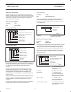
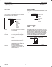
GoodLink
Good downstream USB connection indication is provided through
GoodLink
technology. When the port is enabled and there is at
least one valid upstream traffic from the port, the LED indicator will
be ON. The LED indicator will blink on every valid upstream traffic. A
valid upstream traffic is defined as traffic with a good SOP and
terminated by a good EOP. During global suspend, all LEDs will be
OFF.
This feature provides a user-friendly indicator on the status of the
hub, the connected downstream devices and the USB traffic. It is a
useful field diagnostics tool to isolate the faulty equipment. This
feature helps lower the field support and the hotline costs.