


Philips Semiconductors Product specification
PDIUSBH12USB 2-port hub
1999 Jul 22
5
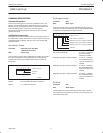
ENDPOINT DESCRIPTIONS
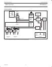
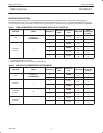
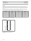
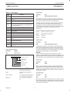
There are two endpoint configuration modes supported by the PDIUSBH12, the Single Embedded Function mode and the Multiple (3)
Embedded Function mode. The Single Embedded Function mode is the default at power up reset. The Multiple (3) Embedded Function mode
can be configured by writing a zero to bit 7 of the first byte of the Set Mode command. Either mode is backward compatible to the PDIUSBH11.
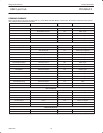
Table 1. SINGLE EMBEDDED FUNCTION MODE (DEFAULT AT POWER UP)
FUNCTION PORTS ENDPOINT #
ENDPOINT
INDEX
TRANSFER
TYPE
DIRECTION
MAX
PACKET SIZE
(BYTES)
0U t
0
0
Control
OUT 8
Hub
0: Upstream
2–3: Downstream
0
1
Control
IN 8
2
–
3:
Downstream
1
–
Interrupt
IN 1
0
2
Control
OUT 8
0
3
Control
IN 8
1
5
Generic
OUT 8
Embedded
1
1
4
Generic
IN 8
Function 1
1
2
6
Generic
OUT 8
2
7
Generic
IN 8
3
8
Generic
OUT 8
3
9
Generic
IN 8
NOTE:
1. Hub interrupt endpoint is not indexed.
2. Generic endpoint can be used for Interrupt or Bulk endpoint.
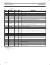
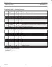
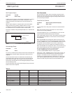
Table 2. MULTIPLE (3) EMBEDDED FUNCTION MODE
FUNCTION PORTS ENDPOINT #
ENDPOINT
INDEX
TRANSFER
TYPE
DIRECTION
MAX
PACKET SIZE
(BYTES)
0U t
0
0
Control
OUT 8
Hub
0: Upstream
2–3: Downstream
0
1
Control
IN 8
2
–
3:
Downstream
1 – Interrupt IN 1
0
2
Control
OUT 8
Embedded
1
0
3
Control
IN 8
Function 1
1
1
5
Generic
OUT 8
1
4
Generic
IN 8
0
10
Control
OUT 8
Embedded
6
0
11
Control
IN 8
Function 6
6
1
6
Generic
OUT 8
1
7
Generic
IN 8
0
12
Control
OUT 8
Embedded
7
0
13
Control
IN 8
Function 7
7
1
8
Generic
OUT 8
1
9
Generic
IN 8