


Philips Semiconductors Product specification
PDIUSBH12USB 2-port hub
1999 Jul 22
14
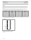
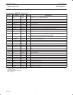
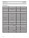
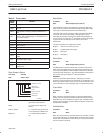
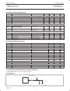
Table 3. Error codes
ERROR
CODE
RESULT
0000 No Error
0001
PID encoding Error; bits 7–4 are not the inversion of
bits 3–0
0010
PID unknown; encoding is valid, but PID does not
exist
0011
Unexpected packet; packet is not of the type expected
(= token, data or acknowledge), or SETUP token to a
non-control endpoint
0100 Token CRC Error
0101 Data CRC Error
0110 Time Out Error
0111 Babble Error
1000 Unexpected End-of-packet
1001 Sent or received NAK
1010
Sent Stall, a token was received, but the endpoint was
stalled
1011
Overflow Error, the received packet was longer than
the available buffer space
1101 Bitstuff Error
1111
Wrong DATA PID; the received DATA PID was not the
expected one
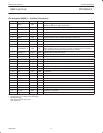
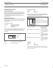
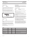
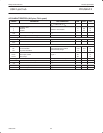
Read Endpoint Status
Command : 80–8Dh
Data : Read 1 byte
POWER ON VALUE
RESERVED
SETUP PACKET
STALL
DATA 0/1 PACKET
BUFFER FULL
765432
X
1
X
0
0000XX
SV00833
RESERVED
Setup Packet A ‘1’ indicates the last received
packet had a SETUP token.
STALL A ‘1’ indicates the endpoint is
stalled.
Data 0/1 Packet A ‘1’ indicates if the last received
or sent packet had a DATA1 PID.
Buffer Full A ‘1’ indicates that the buffer is
full.
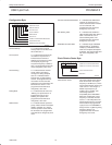
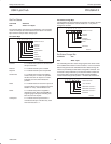
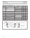
Read Buffer
Command : F0h
Data : Read multiple bytes (max 10)
The Read Buffer command is followed by a number of data reads,
which return the contents of the selected endpoint data buffer. After
each read, the internal buffer pointer is incremented by 1.
The buffer pointer is not reset to the buffer start by the Read Buffer
command. This means that reading or writing a buffer can be
interrupted by any other command (except for Select Endpoint), or
can be done by more than one I
2
C transaction (read the first 2 bytes
to get the number of data bytes, then read the rest in other
transactions).
The data in the buffer are organized as follows:
• byte 0: Reserved: can have any value
• byte 1: Number/length of data bytes
• byte 2: Data byte 1
• byte 3: Data byte 2
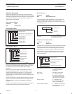
Write Buffer
Command : F0h
Data : Write multiple bytes (max 10)
The Write Buffer command is followed by a number of data writes,
which load the endpoints buffer. The data must be organized in the
same way as described in the Read Buffer command. The first byte
(reserved) should always be 0. As in the Read Buffer command, the
data can be split up into different I
2
C data transactions.
WARNING:
There is no protection against writing or reading over a buffer’s
boundary or against writing into an OUT buffer or reading from an IN
buffer. Any of these actions could cause an incorrect operation. Data
in an OUT buffer are only meaningful after a successful transaction.
Clear Buffer
Command : F2h
Data : None
When a packet is received completely, an internal endpoint buffer
full flag is set. All subsequent packets will be refused by returning a
NAK. When the microcontroller has read the data, it should free the
buffer by the Clear Buffer command. When the buffer is cleared new
packets will be accepted.
Validate Buffer
Command : FAh
Data : None
When the microprocessor has written data into an IN buffer, it should
set the buffer full flag by the Validate Buffer command. This indicates
that the data in the buffer are valid and can be sent to the host when
the next IN token is received.