


Philips Semiconductors Product specification
PDIUSBH12USB 2-port hub
1999 Jul 22
13
Data Flow Commands
Data flow commands are used to manage the data transmission
between the USB endpoints and the monitor. Much of the data flow
is initiated via an interrupt to the microcontroller. The microcontroller
utilizes these commands to access and determine whether the
endpoint FIFOs have valid data.
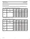
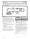
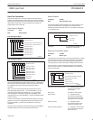
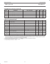
Read Interrupt Register
Command : F4h
Data : Read 2 bytes
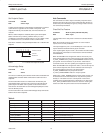
Interrupt Register Byte 1
SV00844
POWER ON VALUE
ENDPOINT INDEX 4
ENDPOINT INDEX 5
ENDPOINT INDEX 6
ENDPOINT INDEX 7
765432
0
1
0
0
000000
ENDPOINT INDEX 1 (HUB CONTROL IN)
ENDPOINT INDEX 2
ENDPOINT INDEX 3
ENDPOINT INDEX 0 (HUB CONTROL OUT)
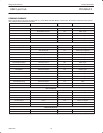
Interrupt Register Byte 2
SV00845
POWER ON VALUE
ENDPOINT INDEX 12
ENDPOINT INDEX 13
BUS RESET
RESERVED
765432
0
1
0
0
0000X0
ENDPOINT INDEX 9
ENDPOINT INDEX 10
ENDPOINT INDEX 11
ENDPOINT INDEX 8
This command indicates the origin of an interrupt. A ‘1’ indicates an
interrupt occurred at this endpoint. The bits are cleared by reading
the endpoint status register through Read Endpoint Status
command.
After a bus reset an interrupt will be generated and bit 6 of the
Interrupt Register Byte 2 will be ‘1’. [In the PDIUSBH11, the bus
reset event is indicated by the absence of a ‘1’ in any bit of the
Interrupt Register. Note that the backward compatibility is still
maintained because in the PDIUSBH11, the Interrupt Register Byte
2 does not exist.]
The bus reset interrupt is internally cleared by reading the interrupt
register. A bus reset is completely identical to the hardware reset
through the RESET_N pin with the sole difference of interrupt
notification.
The hub interrupt endpoint is handled internally by the PDIUSBH12
hardware without the need of microcontroller intervention.
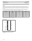
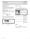
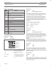
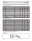
Select Endpoint
Command : 00-0Dh
Data : Optional Read 1 byte
The Select Endpoint command initializes an internal pointer to the
start of the Selected buffer. Optionally, this command can be
followed by a data read, which returns ‘0’ if the buffer is empty and
‘1’ if the buffer is full.
765432
X
1
0
0
POWER ON VALUE
FULL/EMPTY
RESERVED
XXXXXX
SV00831
Full/Empty A ‘1’ indicates the buffer is full, ‘0’
indicates an empty buffer.
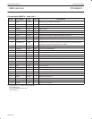
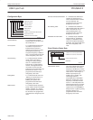
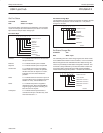
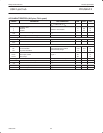
Read Last Transaction Status
Command : 40–4Dh
Data : Read 1 byte
The Read Last Transaction Status command is followed by one data
read that returns the status of the last transaction of the endpoint.
This command also resets the corresponding interrupt flag in the
interrupt register, and clears the status, indicating that it was read.
This command is useful for debugging purposes. Since it keeps
track of every transaction, the status information is overwritten for
each new transaction.
POWER ON VALUE
DATA RECEIVE/TRANSMIT SUCCESS
ERROR CODE (SEE TABLE)
SETUP PACKET
DATA 0/1 PACKET
PREVIOUS STATUS NOT READ
765432
0
1
0
0
000000
SV00832
Data Receive/Transmit Success A ‘1’ indicates data has been
received or transmitted
successfully.
Error Code See Table 3, Error Codes.
Setup Packet A ‘1’ indicates the last
successful received packet
had a SETUP token (this will
always read ‘0’ for IN buffers.
Data 0/1 Packet A ‘1’ indicates the last
successful received or sent
packet had a DATA1 PID.
Previous Status not Read A ‘1’ indicates a second event
occurred before the previous
status was read.