


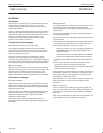

Philips Semiconductors Product specification
PDIUSBH12USB 2-port hub
1999 Jul 22
21
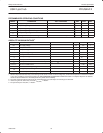
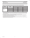
AC CHARACTERISTICS (AI/O pins, LOW speed)
SYMBOL PARAMETER TEST CONDITIONS MIN MAX UNIT
Driver characteristics
C
L
= 50pF and 350pF;
R
pu
= 1.5kΩ on D– to V
CC
Transition Time Between 10% and 90%
t
Rise time
C
L
= 50pF 75 ns
t
lr
Rise
time
C
L
= 350pF 300 ns
t
f
Fall time
C
L
= 50pF 75 ns
t
lf
Fall
time
C
L
= 350pF 300 ns
t
RFM
Rise/fall time matching (t
r
/t
f
) 80 120 %
V
LCRS
Output signal crossover voltage 1.3 2.0 V
Driver Timings
t
LEOPT
Source EOP width Figure 1 1.25 1.50 µs
t
LDEOP
Differential data to EOP transition skew Figure 1 –40 100 ns
Receiver Timings
EOP Width at Receiver
t
LEOPR1
Must reject as EOP
Figure 1
330 ns
t
LEOPR2
Must accept
Fig
u
re
1
675 ns
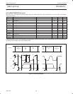
Hub Timings Low Speed downstream port.
t
LHDD
Hub Differential Data Delay Figure 2 300 ns
t
LSOP
Data bit width distortion after SOP Figure 2 –65 45 ns
t
LEOPDR
Hub EOP Delay Relative to T
HDD
Figure 3 0 200 ns
t
LHESK
Hub EOP Output Width Skew Figure 3 –300 +300 ns
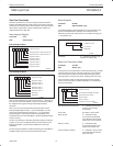
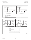
SV00837
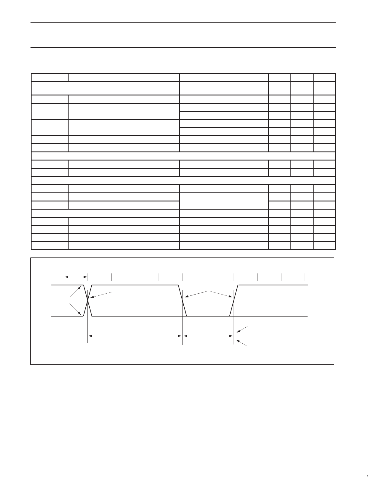
t
PERIOD
DIFFERENTIAL
DATA LINES
CROSSOVER POINT
CROSSOVER POINT
EXTENDED
DIFFERENTIAL DATA TO
SEO/EOP SKEW
N * t
PERIOD
+ t
DEOP
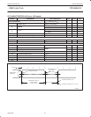
SOURCE EOP WIDTH: t
EOPT
RECEIVER EOP WIDTH: t
EOPR1
, t
EOPR2
Figure 1. Differential data to EOP transition skew and EOP width