


Philips Semiconductors Product specification
PDIUSBH12USB 2-port hub
1999 Jul 22
8
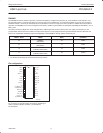
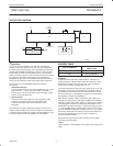
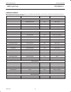
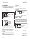
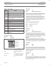
Pin description (MODE 1 – Individual Overcurrent)
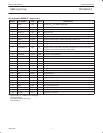
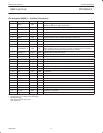
PIN NO PIN SYMBOL TYPE DRIVE DESCRIPTION
1 TEST1 Input
Connect to V
CC
for 48MHz crystal input.
Connect to Ground for 12MHz crystal input.
2 TEST2 Input Connect to V
CC
3 TEST3 Input Connect to Ground
4 RESET_N Input ST Power-on reset
5 GND Power Ground reference
6 XTAL1 Input Crystal connection 1 (48 or 12MHz depending on TEST1 pin)
7 XTAL2 Output Crystal connection 2 (48 or 12MHz depending on TEST1 pin)
8 CLKOUT Output 3mA Programmable output clock for external devices
9 V
CC
Power Voltage supply 3.3V ± 0.3V
10 OCURRENT2_N Input ST
Downstream port 2 over-current notice. This pin is also use to sense the USB
VBUS. A LOW on this pin of less than 2 seconds is interpreted as an overcurrent
notice; longer than 2 seconds is interpreted as loss of VBUS.
11 SWITCH_N Output OD6 Enables power to downstream ports
12 SUSPEND Output OD6 Device is in suspended state
13 DN2_GL_N Output OD6 Downstream port 2 GoodLink LED indicator
14 OCURRENT3_N Input ST Downstream port 3 over-current notice
15 RSVD Input Reserved. Connect to GND for normal operation.
16 RSVD Input Reserved. Connect to GND for normal operation.
17 INT_N Output OD6 Connect to microcontroller interrupt
18 SDA I/O OD6 I
2
C bi-directional data
19 SCL I/O OD6 I
2
C bit-clock
20 GND Power Ground reference
21 DN3_DP AI/O Downstream port 3 D
+
connection
22 DN3_DM AI/O Downstream port 3 D
–
connection
23 DN2_DP AI/O Downstream port 2 D
+
connection
24 DN2_DM AI/O Downstream port 2 D
-
connection
25 AGND Power Analog Ground reference
26 AV
CC
Power Analog voltage supply 3.3V ± 0.3V
27 UP_DP AI/O Upstream D
+
connection
28 UP_DM AI/O Upstream D
-
connection
NOTE:
1. Signals ending in _N indicate active low signals.
ST: Schmitt Trigger
OD6: Open Drain with 6 mA drive
AI/O: Analog I/O