


Philips Semiconductors Product specification
PDIUSBH12USB 2-port hub
1999 Jul 22
9
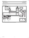
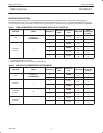
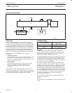
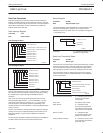
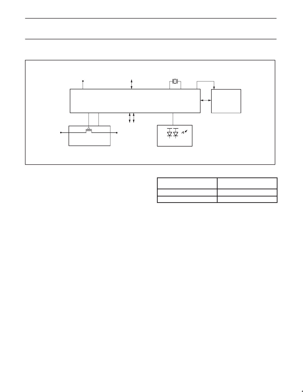
APPLICATION DIAGRAM
I
2
C
GOODLINK LED
POWER SWITCH
AND
OVERCURRENT CIRCUIT
5V
SWITCHED
5V
H12
µC
CLKOUT
12MHz
USB
DOWNSTREAM
USB
UPSTREAM
3.3V
SV00853
I
2
C Interface
The I
2
C bus is used to interface to an external microcontroller
needed to control the operation of the hub. For cost consideration,
the target system microcontroller can be shared and utilized for this
purpose. The PDIUSBH12 implements a slave I
2
C interface. When
the PDIUSBH12 needs to communicate with the microcontroller it
asserts an interrupt signal. The microcontroller services this interrupt
by reading the appropriate status register on the PDIUSBH12
through the I
2
C bus. (For more information about the I
2
C serial bus,
refer to the
I
2
C Handbook
, Philips order number 9397 750 00013).
The I
2
C interface on the PDIUSBH12 defines two types of
transactions:
1. command transaction
A command transaction is used to define which data (e.g., status
byte, buffer data, ...) will be read from / written to the USB
interface in the next data transaction. A data transaction usually
follows a command transaction.
2. data transaction
A data transaction reads data from / writes data to the USB
interface. The meaning of the data is dependent on the
command transaction which was sent before the data
transaction.
Two addresses are used to differentiate between command and
data transactions. Writing to the command address is interpreted as
a command, while reading from / writing to the data address is used
to transfer data between the PDIUSBH12 and the controller.
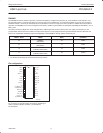
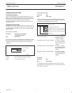
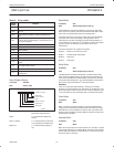
ADDRESS TABLE
TYPE OF ADDRESS
PHYSICAL ADDRESS
(MSB to LSB)
Command 0011 011 (binary)
Data 0011 010 (binary)
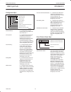
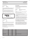
Protocol
An I
2
C transaction starts with a ‘Start Condition’, followed by an
address. When the address matches either the command or data
address the transaction starts and runs until a ‘Stop Condition’ or
another ‘Start Condition’ (repeated start) occurs.
The command address is write-only and is unable to do a read. The
next bytes in the message are interpreted as commands. Several
command bytes can be sent after one command address. Each of
the command bytes is acknowledged and passed on to the Memory
Management Unit inside the PDIUSBH12.
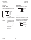
When the start condition address matches the data address, the
next bytes are interpreted as data. When the RW bit in the address
indicates a ‘master writes data to slave’ (=‘0’) the bytes are received,
acknowledged and passed on to the Memory Management Unit. If
the RW bit in the address indicates a ‘master reads data from slave’
(=‘1’) the PDIUSBH12 will send data to the master. The I
2
C-master
must acknowledge all data bytes except the last one. In this way the
I
2
C interface knows when the last byte has been transmitted and it
then releases the SDA line so that the master controller can
generate the STOP condition.
Repeated start support allows another packet to be sent without
generating a Stop Condition.
Timing
The I
2
C interface in the PDIUSBH12 can support clock speeds up to
1MHz.